Manuals
/
HP
/
Computer Equipment
/
Computer Hardware
HP
BladeSystem Enclosure technologies
manual
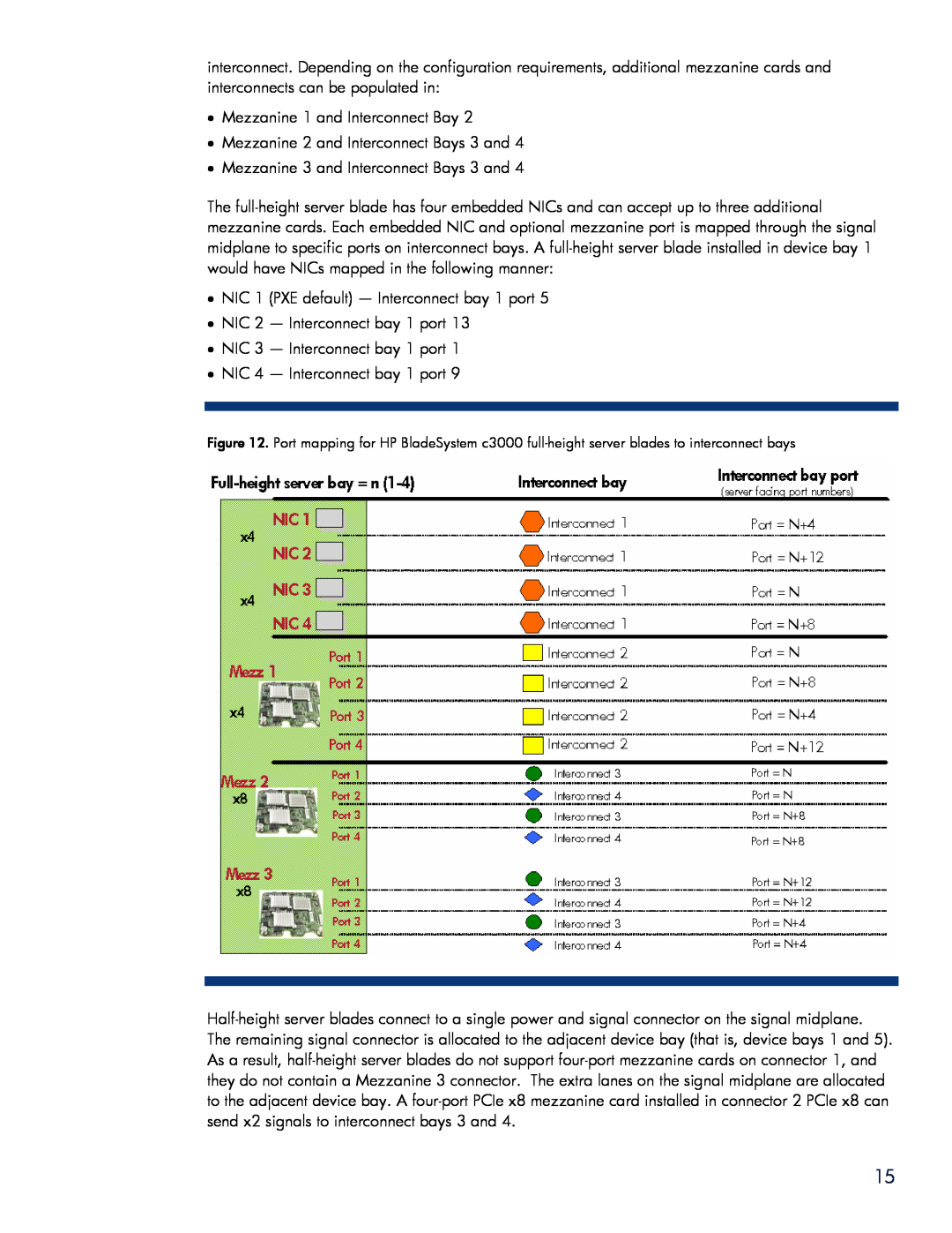
Mezzanine 1 and Interconnect Bay
Models:
BladeSystem Enclosure technologies
1
15
28
28
Download
28 pages
41.5 Kb
12
13
14
15
16
17
18
19
Onboard Administrator
Command-line interface
HP BladeSystem Power Sizer
Page 15
Image 15
Page 14
Page 16
Page 15
Image 15
Page 14
Page 16
Contents
technology brief
HP BladeSystem c3000 Enclosure technologies
Overview of HP BladeSystem c3000 Enclosure
Abstract
Page
HP Thermal Logic technologies
Active Cool fans
Figure 4. HP BladeSystem c3000 self-sealing enclosure
HP PARSEC architecture
Thermal Logic for the server blade and enclosure
Power supplies and enclosure power subsystem
HP BladeSystem Power Sizer
Pooled power
Connecting with no power redundancy configured
Figure 9. Diagram of the HP BladeSystem c3000 signal midplane
Interconnect options and infrastructure
Fabric connectivity and port mapping
Several port types are referenced in Figures 12 and
Mezzanine 1 and Interconnect Bay
Virtual Connect
Enclosure-based DVD ROM
Onboard Administrator
Page
Insight Display
Enclosure link cabling
Command-line interface
Onboard Administrator cabling
Web GUI
Summary
Recommendations
The following acronyms are used in the text of this document
Appendix A. Acronyms in text
Appendix B. Fan, power supply, and device bay population guidelines
All power supply bays filled
Table B-1. Power supply placement
Number of power supplies
Power supply bays used
Page
8 half-height server blades with both full-height dividers installed
Page
Send comments about this paper to TechCom@HP.com
For more information
Call to action
For additional information, refer to the resources listed below
Top
Page
Image
Contents