Manuals
/
HP
/
Computer Equipment
/
Laptop
HP
CQ35-127TX Where used 2 screws that secure the system board to the computer, Screw listing
Models:
CQ35-103TX
CQ35-230TX
CQ35-126TX
CQ35-220TU
CQ35-227TX
1
113
135
135
Download
135 pages
21.22 Kb
110
111
112
113
114
115
116
117
<
>
Specifications
Install
Removal and replacement procedures
Maintenance
System Configuration menu
wireless antennas built into display assembly
Setup Utility
Display assembly subcomponents
Signal
Backup and recovery
Page 113
Image 113
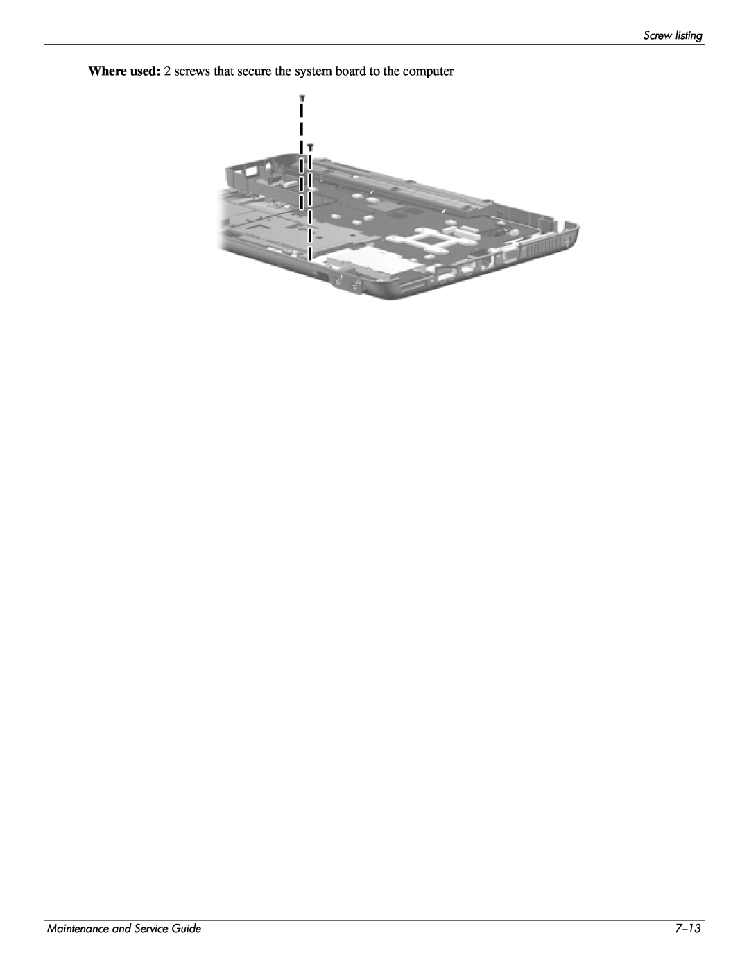
Screw listing
Where used:
2 screws that secure the system board to the computer
Maintenance and Service Guide
7–13
Page 112
Page 114
Page 113
Image 113
Page 112
Page 114
Contents
Document Part Number
Maintenance and Service Guide
Compaq Presario CQ35 Notebook PC
Page
First Edition May Document Part Number
Copyright 2009 Hewlett-Packard Development Company, L.P
Safety warning notice
1 Product description 2 External component identification
4 Removal and replacement procedures
3 Illustrated parts catalog
Contents
6 Specifications
5 Setup Utility
8 Backup and recovery
7 Screw listing
10Power cord set requirements
9 Connector pin assignments
11Recycling
Index
Maintenance and Service Guide
Continued
Product description
Maintenance and Service Guide
Discrete graphics
Product description
UMA graphics
Category
Product description
Maintenance and Service Guide
Continued
Continued
2 wireless antennas built into display assembly
Product description
Maintenance and Service Guide
Power requirements
Discrete graphics
UMA graphics
WWAN module
Hard drive Memory modules RTC battery Optical drive WLAN module
Product description
Top components
External component identification
Display components
Maintenance and Service Guide
External component identification
Buttons and fingerprint reader select models only
Maintenance and Service Guide
Keys
esc key
fn key
External component identification
Lights
External component identification
Pointing devices
Maintenance and Service Guide
External component identification
Front components
Left-side components
External component identification
Right-side components
Maintenance and Service Guide
region. If you replace the module and then receive a warning message
Bottom components
External component identification
Maintenance and Service Guide
Service tag
Illustrated parts catalog
Illustrated parts catalog
Computer major components
Maintenance and Service Guide
Illustrated parts catalog
Maintenance and Service Guide
Item Description
Continued
Illustrated parts catalog
Battery
Item Description
Intel Core2 Duo processors
Continued
Maintenance and Service Guide
Broadcom 4322AGN 802.11a/b/g/n WLAN module for use in Canada
20 WLAN module continued 802.11a/b/g WLAN module
Illustrated parts catalog
Item Description
Illustrated parts catalog
Display assembly subcomponents
Maintenance and Service Guide
Maintenance and Service Guide
Plastics Kit
Illustrated parts catalog
1 ExpressCard slot bezel
Maintenance and Service Guide
Mass storage devices
Illustrated parts catalog
Item Description
Power cords
Miscellaneous parts
Illustrated parts catalog
Description
Maintenance and Service Guide
Sequential part number listing
Illustrated parts catalog
Continued
Spare part number
Illustrated parts catalog
Description
Continued
Spare part number
Maintenance and Service Guide
Description
Continued
Spare part number
Illustrated parts catalog
Description
3-14
Preliminary replacement requirements
Removal and replacement procedures
Service considerations
Cables and connectors
Electrostatic discharge damage
Grounding guidelines
Drive handling
Packaging and transporting guidelines
Equipment guidelines
Workstation guidelines
Service tag
Component replacement procedures
Computer feet
Battery
Remove the battery
Hard drive
7. Remove the hard drive 4 from the hard drive bay
Memory module
Removal and replacement procedures
WLAN module
Maintenance and Service Guide
Continued
Removal and replacement procedures
4. Remove the battery see “Battery” on page
Before removing the WLAN module, follow these steps
2. Disconnect all external devices connected to the computer
Remove the WLAN module
Reverse this procedure to install the WLAN module
Removal and replacement procedures
RTC battery
Optical drive
a. Position the optical drive with the rear toward you
Keyboard
2. Turn the computer display-side up with the front toward you
Keyboard cover
2. Turn the computer display-side up with the front toward you
c. Keyboard cover see “Keyboard cover” on page
Right speaker
b. Keyboard see “Keyboard” on page
a. Hard drive see “Hard drive” on page
Top cover
b. Optical drive see “Optical drive” on page
c. Keyboard see “Keyboard” on page
Remove the top cover
3. Disconnect the left speaker cable 1 from the system board
Removal and replacement procedures
Reverse this procedure to install the top cover
Maintenance and Service Guide
12. Lift the rear edge 1 of the top cover until it rests at an angle
f. Top cover see “Top cover” on page
Fingerprint reader board
a. Hard drive see “Hard drive” on page
b. Optical drive see “Optical drive” on page
a. Hard drive see “Hard drive” on page
Left speaker
b. Optical drive see “Optical drive” on page
c. Keyboard see “Keyboard” on page
g. Left speaker see “Left speaker” on page
Display assembly
a. Hard drive see “Hard drive” on page
b. Optical drive see “Optical drive” on page
Remove the display assembly
531800-001-for use only with computer models equipped with a webcam
8. Disconnect the webcam module cable 2 from the webcam module
12. If it is necessary to replace the display hinges, remove the six Phillips PM2.0×3.0 screws 1 that secure the hinges to the display panel
17. If it is necessary to replace the wireless antenna transceivers and cables, release the tabs 1 built into the display enclosure shielding
Reverse this procedure to reassemble and install the display assembly
a. Hard drive see “Hard drive” on page
LED board
b. Optical drive see “Optical drive” on page
c. Keyboard see “Keyboard” on page
a. Hard drive see “Hard drive” on page
Bluetooth module
b. Optical drive see “Optical drive” on page
c. Keyboard see “Keyboard” on page
a. Hard drive see “Hard drive” on page
Audio board
b. Optical drive see “Optical drive” on page
c. Keyboard see “Keyboard” on page
a. Hard drive see “Hard drive” on page
USB board
b. Optical drive see “Optical drive” on page
c. Keyboard see “Keyboard” on page
e. Display assembly see “Display assembly” on page
Power connector and cable
a. Hard drive see “Hard drive” on page
b. Optical drive see “Optical drive” on page
RTC battery see “RTC battery” on page
j. Display assembly see “Display assembly” on page
Heat sink see “Fan/heat sink assembly” on page
System board
Removal and replacement procedures
2 Bluetooth module cable 3 Audio board cable
Maintenance and Service Guide
Remove the system board
Reverse this procedure to install the system board
k. System board see “System board” on page
Fan/heat sink assembly
j. Display assembly see “Display assembly” on page
a. Hard drive see “Hard drive” on page
Remove the fan/heat sink assembly
The thermal material must be thoroughly cleaned from the surfaces of the fan/heat sink assembly and the system board each time the fan/heat sink assembly is removed
5. Remove the fan/heat sink assembly
Reverse this procedure to install the fan/heat sink assembly
Processor
d. RTC battery see “RTC battery” on page
e. Optical drive see “Optical drive” on page
f. Keyboard see “Keyboard” on page
j. Top cover see “Top cover” on page
i. Display assembly see “Display assembly” on page
k. System board see “System board” on page
2. Lift the processor 2 straight up and remove it
Starting the Setup Utility
Setup Utility
Using the Setup Utility
Changing the language of the Setup Utility
Restoring default settings in the Setup Utility
Navigating and selecting in the Setup Utility
Displaying system information
Setup Utility
Exiting the Setup Utility
Setup Utility menus
Main menu
Security menu
Setup Utility
System Configuration menu
Diagnostics menu
Maintenance and Service Guide
Specifications
Computer specifications
Specifications
13.3-in display specifications
Specifications
Hard drive specifications
Maintenance and Service Guide
Specifications
Blu-ray ROM DVD±R/RW SuperMulti DL Drive specifications
Access time
Applicable disc
Specifications
DVD±RW and CD-RW SuperMulti Double-Layer Drive specifications
Access time
Transfer mode
Specifications
System DMA specifications
Hardware
DMA System function
Specifications
System memory map specifications
Maintenance and Service Guide
Size
Specifications
System interrupt specifications
Hardware IRQ
System function
Specifications
System I/O address specifications
System function shipping configuration
Maintenance and Service Guide
System function shipping configuration
Specifications
I/O address hex
6-10
Phillips PM2.5×6.0 captive screw
Where used
Screw listing
Screw listing
Phillips PM3.0×4.0 screw
Maintenance and Service Guide
Where used One screw that secures the right speaker to the computer
Phillips PM2.0×4.0 screw
Maintenance and Service Guide
Screw listing
Where used
Where used 5 screws that secure the top cover to the computer
Maintenance and Service Guide
1 One screw that secures the LED board to the base enclosure
Where used
Phillips PM2.0×9.0 screw
Maintenance and Service Guide
1 One screw that secures the optical drive to the computer
Screw listing
Phillips PM2.0×3.0 screw
Maintenance and Service Guide
Where used 2 screws that secure the optical drive bracket to the optical drive
Screw listing
Maintenance and Service Guide
Where used 2 screws that secure the keyboard cover to the computer
Phillips PM2.5×9.0 screw
Maintenance and Service Guide
Screw listing
Where used
Phillips PM2.0×2.5 broadhead screw
Where used 2 screws that secure the display assembly to the computer
Phillips PM2.5×6.0 screw
Maintenance and Service Guide
Screw listing
Maintenance and Service Guide
Phillips PM2.5×4.0 screw
Screw listing
7-12
Maintenance and Service Guide
Where used 2 screws that secure the system board to the computer
Screw listing
7-13
Maintenance and Service Guide
Phillips PM2.0×7.0 captive screw
Screw listing
7-14
Overview
Backup and recovery
Creating recovery discs
Backup suggestions
When to back up
3. Click Recovery disc creation, and then click Next
Backing up your information
When to create restore points
Using system restore points
Create a system restore point
Restore to a previous date and time
Recovering from the recovery discs
Performing a recovery
Recovering from the dedicated recovery partition select models only
Select Start All Programs Recovery Manager Recovery Manager
Audio-in microphone
Connector pin assignments
Audio-out headphone
Maintenance and Service Guide
Connector pin assignments
External monitor
Connector pin assignments
HDMI
Signal
Maintenance and Service Guide
Universal Serial Bus
RJ-45 network
Connector pin assignments
Signal
Requirements for all countries and regions
Power cord set requirements
Power cord set requirements
Requirements for specific countries and regions
Country/region
Accredited agency
Display
Battery
Recycling
Maintenance and Service Guide
Perform the following steps to disassemble the display assembly
3. Remove the display bezel
Recycling
6. Remove the display panel assembly 2 from the display enclosure
10. Remove the display panel frame 2 from the display panel
16. Turn the display panel upside down
Maintenance and Service Guide
17. Remove the backlight frame from the display panel
18. Remove the backlight from the backlight frame
19. Disconnect the display cable 1 from the LCD panel
Maintenance and Service Guide
21. Release the LCD panel 3 from the display rear panel
23. Remove the LCD panel 24. Recycle the LCD panel and backlight
Index
Page
Page
Page
Index-5