INSTALLATION INSTRUCTIONS
Thermostat Wiring Connections
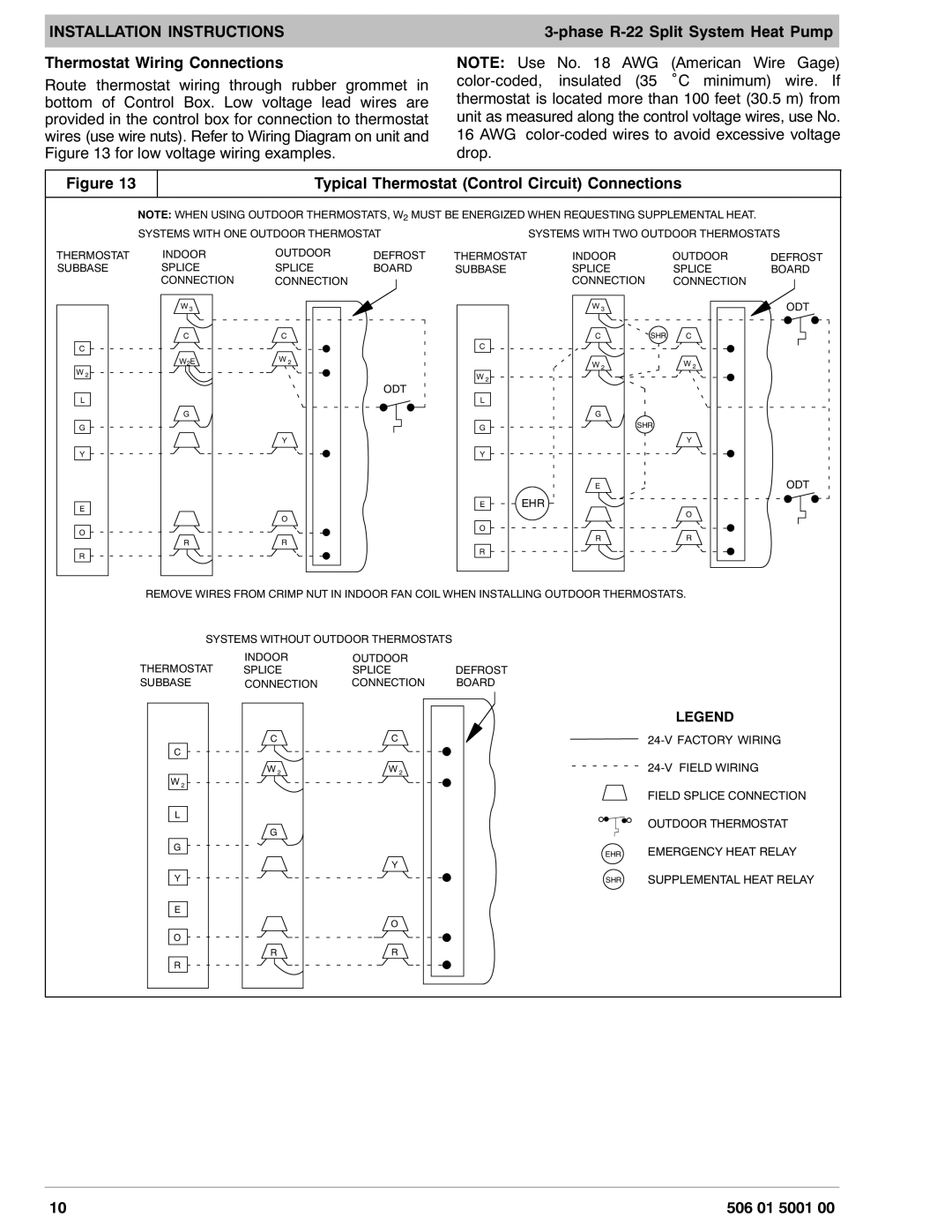
Route thermostat wiring through rubber grommet in bottom of Control Box. Low voltage lead wires are provided in the control box for connection to thermostat wires (use wire nuts). Refer to Wiring Diagram on unit and Figure 13 for low voltage wiring examples.
NOTE: Use No. 18 AWG (American Wire Gage)
Figure 13 |
| Typical Thermostat (Control Circuit) Connections |
| ||||||
| NOTE: WHEN USING OUTDOOR THERMOSTATS, W2 MUST BE ENERGIZED WHEN REQUESTING SUPPLEMENTAL HEAT. |
| |||||||
| SYSTEMS WITH ONE OUTDOOR THERMOSTAT |
|
| SYSTEMS WITH TWO OUTDOOR THERMOSTATS | |||||
THERMOSTAT | INDOOR | OUTDOOR | DEFROST | THERMOSTAT | INDOOR |
| OUTDOOR | DEFROST | |
SUBBASE | SPLICE | SPLICE | BOARD | SUBBASE |
| SPLICE |
| SPLICE | BOARD |
| CONNECTION | CONNECTION |
|
|
| CONNECTION |
| CONNECTION |
|
| W 3 |
|
|
|
| W 3 |
|
| ODT |
| C | C |
|
|
| C | SHR | C |
|
C |
|
|
| C |
|
|
|
|
|
|
|
|
|
|
|
|
|
| |
W 2 | W2E | W 2 |
|
|
| W 2 |
| W 2 |
|
|
|
| W 2 |
|
|
|
|
| |
|
|
| ODT |
|
|
|
|
| |
|
|
|
|
|
|
|
|
| |
L |
|
|
| L |
|
|
|
|
|
| G |
|
|
|
| G |
|
|
|
G |
|
|
| G |
| SHR |
|
| |
|
|
|
|
|
|
|
| ||
|
| Y |
|
|
|
|
| Y |
|
Y |
|
|
| Y |
|
|
|
|
|
|
|
|
|
|
| E |
|
| ODT |
E |
|
|
| E | EHR |
|
|
| |
|
|
|
|
|
|
| O |
| |
|
| O |
|
|
|
|
|
| |
|
|
|
|
|
|
|
|
| |
O |
|
|
| O |
|
|
|
|
|
|
|
|
|
| R |
| R |
| |
| R | R |
|
|
|
|
| ||
|
|
|
|
|
|
|
| ||
R |
|
|
| R |
|
|
|
|
|
|
|
|
|
|
|
|
|
| |
| REMOVE WIRES FROM CRIMP NUT IN INDOOR FAN COIL WHEN INSTALLING OUTDOOR THERMOSTATS. |
| |||||||
| SYSTEMS WITHOUT OUTDOOR THERMOSTATS |
|
|
|
|
|
| ||
| THERMOSTAT | INDOOR | OUTDOOR |
|
|
|
|
|
|
| SPLICE | SPLICE | DEFROST |
|
|
|
|
| |
| SUBBASE | CONNECTION | CONNECTION | BOARD |
|
|
|
|
|
|
|
|
|
|
|
|
| LEGEND |
|
|
| C | C |
|
|
| 24 |
|
|
| C |
|
|
|
|
|
|
|
|
|
| W 2 | W 2 |
|
|
| 24 FIELD WIRING |
| |
| W 2 |
|
|
|
|
|
|
|
|
|
|
|
|
|
|
| FIELD SPLICE CONNECTION | ||
| L |
|
|
|
|
| OUTDOOR THERMOSTAT | ||
|
| G |
|
|
|
| |||
|
|
|
|
|
|
|
|
| |
| G |
|
|
|
| EHR | EMERGENCY HEAT RELAY | ||
|
|
|
|
|
| ||||
|
|
| Y |
|
|
|
|
|
|
| Y |
|
|
|
| SHR | SUPPLEMENTAL HEAT RELAY | ||
| E |
|
|
|
|
|
|
|
|
|
|
| O |
|
|
|
|
|
|
| O |
|
|
|
|
|
|
|
|
|
| R | R |
|
|
|
|
|
|
| R |
|
|
|
|
|
|
|
|
10 |
|
|
|
|
|
|
| 506 01 5001 00 | |
