INSTALLATION INSTRUCTIONS
NOTE: These are not
The service valve cap is a primary seal for the valve and must be properly tightened to prevent leaks. Make sure cap is clean and apply refrigerant oil to threads and sealing surface on inside of cap.
Tighten cap finger tight and then tighten additional 6 of a turn (1 wrench flat) to properly seat the sealing surfaces.
J. GAUGE PORTS
Check for leaks at the schrader ports and tighten valve cores if necessary. Install plastic caps finger tight.
ELECTRICAL WIRING
!![]() WARNING
WARNING
ELECTRICAL SHOCK HAZARD
Failure to follow this warning could result in per‐ sonal injury or death.
Before installing, modifying or servicing system, turn OFF the main (remote) electrical disconnect device. There may be more than one disconnect device.
Refer to unit rating plate for the required supply voltage. Depending on the model, required supply voltage will be:
208/230 V,
or
460 V,
Outdoor units are approved for use with copper conductors only. Do not use aluminum wire.
Refer to unit rating plate for minimum circuit ampacity and circuit protection requirements.
Grounding
Permanently ground unit in accordance with the National Electrical Code and local codes or ordinances. Use a copper conductor of the correct size from the grounding lug in control box to a grounded connection in the service panel or a properly driven and electrically grounded ground rod.
Supply Voltage Wiring Connections
Make all outdoor electrical supply (Line Voltage) connections with raintight conduit and fittings. Most codes require a disconnect switch outdoors within sight of the unit. Consult local codes for special requirements.
Route electrical supply (Line Voltage) wiring through knockout hole in bottom of Control Box.
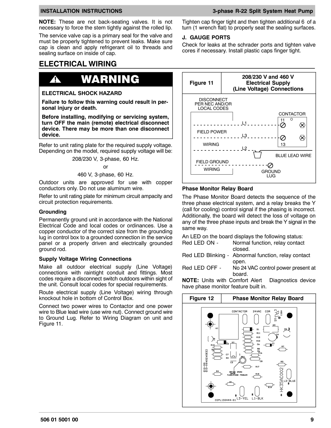
Connect two power wires to Contactor and one power wire to Blue lead wire (use wire nut). Connect ground wire to Ground Lug. Refer to Wiring Diagram on unit and Figure 11.
Figure 11 | 208/230 V and 460 V |
Electrical Supply | |
| (Line Voltage) Connections |
DISCONNECT |
|
PER NEC AND/OR |
|
LOCAL CODES |
|
| CONTACTOR |
| 11 |
| L1 |
FIELD POWER | L3 |
| |
WIRING | 13 |
| L2 |
| BLUE LEAD WIRE |
FIELD GROUND |
|
WIRING | GROUND |
| |
| LUG |
Phase Monitor Relay Board
The Phase Monitor Board detects the sequence of the three phase electrical system, and a relay breaks the Y (call for cooling) control signal if the phasing is incorrect. Additionally, the board will detect the loss of voltage on any of the three phase inputs and break the Y signal in the same way.
An LED on the board displays the following status:
Red LED ON - Normal function, relay contact closed.
Red LED Blinking - Abnormal function, relay contact open.
Red LED OFF - No 24 VAC control power present at board.
NOTE: Units with Comfort Alertt Diagnostics device have phase monitor feature built in.
Figure 12 | Phase Monitor Relay Board | ||||
|
|
|
|
|
|
|
|
|
|
|
|
|
|
|
|
|
|
|
|
|
|
|
|
|
|
|
|
|
|
|
|
|
|
|
|
506 01 5001 00 | 9 |