INSTALLATION INSTRUCTIONS | |
|
|
DEFROST SYSTEM
A. DEFROST THERMOSTAT
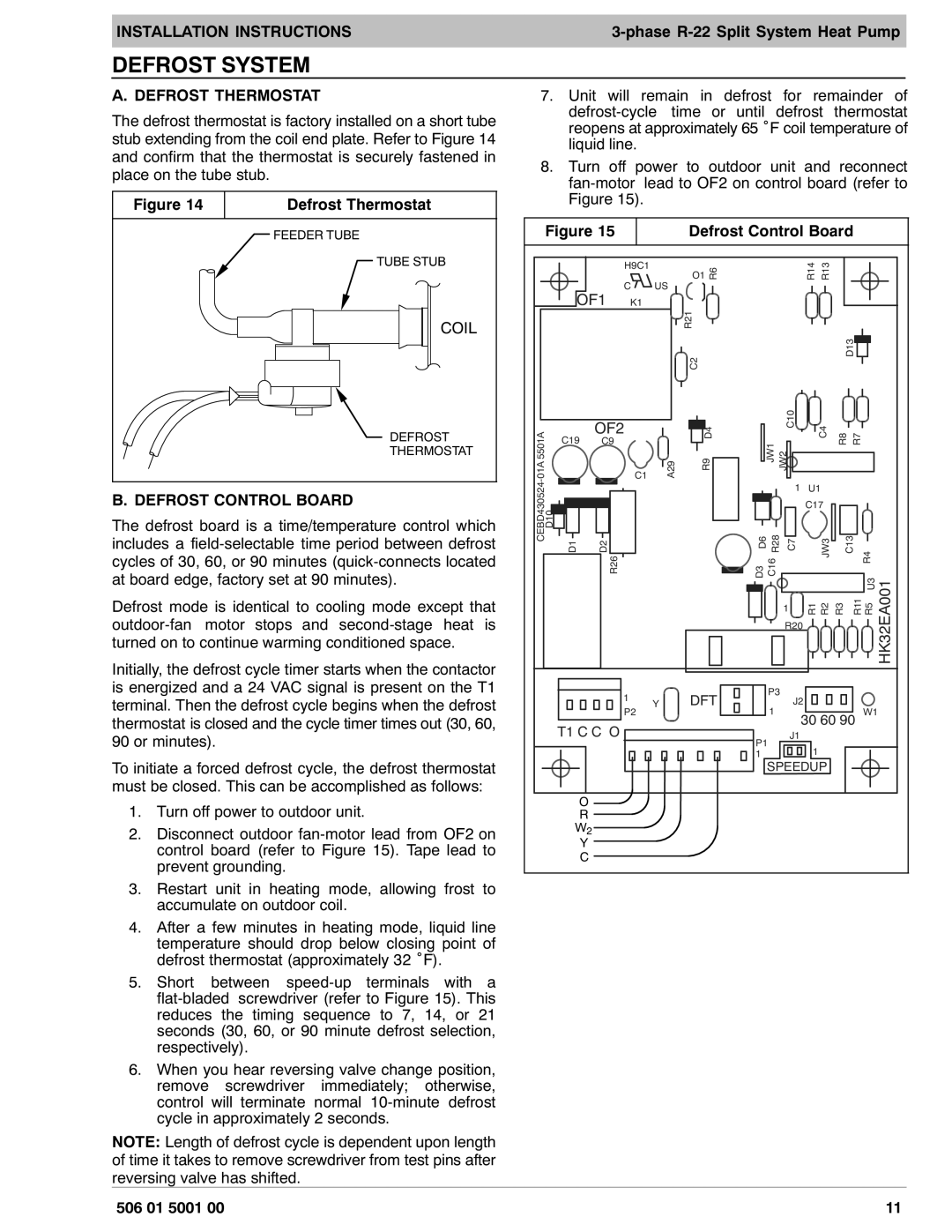
The defrost thermostat is factory installed on a short tube stub extending from the coil end plate. Refer to Figure 14 and confirm that the thermostat is securely fastened in place on the tube stub.
Figure 14 | Defrost Thermostat |
|
|
FEEDER TUBE
TUBE STUB
COIL
DEFROST
THERMOSTAT
B. DEFROST CONTROL BOARD
The defrost board is a time/temperature control which includes a
Defrost mode is identical to cooling mode except that
Initially, the defrost cycle timer starts when the contactor is energized and a 24 VAC signal is present on the T1 terminal. Then the defrost cycle begins when the defrost thermostat is closed and the cycle timer times out (30, 60, 90 or minutes).
To initiate a forced defrost cycle, the defrost thermostat must be closed. This can be accomplished as follows:
1.Turn off power to outdoor unit.
2.Disconnect outdoor
3.Restart unit in heating mode, allowing frost to accumulate on outdoor coil.
4.After a few minutes in heating mode, liquid line temperature should drop below closing point of defrost thermostat (approximately 32 °F).
5.Short between
6.When you hear reversing valve change position, remove screwdriver immediately; otherwise, control will terminate normal
NOTE: Length of defrost cycle is dependent upon length of time it takes to remove screwdriver from test pins after reversing valve has shifted.
7.Unit will remain in defrost for remainder of
8.Turn off power to outdoor unit and reconnect
| Figure 15 |
| Defrost Control Board |
|
| |||||||||
|
|
|
| H9C1→ | O1 | R6 |
|
| R14 R13 |
|
|
|
| |
|
| OF1 | C | US |
|
|
|
|
|
|
|
|
| |
|
| K1 |
|
|
|
|
|
|
|
|
|
| ||
|
|
|
|
|
| R21 |
|
|
|
|
|
|
|
|
|
|
|
|
|
| C2 |
|
|
|
| D13 |
|
|
|
|
|
|
|
|
|
|
|
|
|
|
|
|
| |
01A 5501A |
| C19 | OF2 |
| D4 |
| JW2 C10 | C4 | R8 | R7 |
|
| ||
| C9 |
| JW1 |
|
| |||||||||
|
|
|
|
|
| |||||||||
|
|
| C1 | A29 | R9 |
|
|
| ||||||
- |
|
|
|
|
|
|
|
|
|
|
|
|
| |
CEBD430524 |
|
|
|
|
|
|
|
| 1 | U1 |
|
|
|
|
D10 |
|
|
|
|
|
|
|
| C17 |
|
|
|
| |
D1 | D2 | R26 |
|
| D6 | R28 | C7 | JW3 | C13 |
| R4 |
| ||
|
| D3 | C16 |
| U3 | HK32EA001 | ||||||||
|
|
|
|
|
|
|
|
| 1 |
|
| R11 |
| |
|
|
|
|
|
|
|
|
| R20 |
|
| |||
|
|
|
|
|
|
|
|
|
| R1 R2 | R3 | R5 | ||
|
|
|
| 1 |
| DFT | P3 |
|
|
|
|
| ||
|
|
|
| Y |
| J2 |
|
|
|
| ||||
|
|
|
| P2 | 1 |
|
| W1 |
| |||||
|
|
|
|
|
|
|
| 30 60 90 |
| |||||
|
| T1 C C O |
|
| P1 | J1 |
|
|
|
|
| |||
|
|
|
|
|
|
|
| 1 |
|
|
|
| ||
|
|
|
|
|
|
| 1 |
|
|
|
|
|
| |
|
|
|
|
|
|
|
| SPEEDUP |
|
|
|
| ||
|
| O |
|
|
|
|
|
|
|
|
|
|
|
|
|
| R |
|
|
|
|
|
|
|
|
|
|
|
|
|
| W2 |
|
|
|
|
|
|
|
|
|
|
|
|
|
| Y |
|
|
|
|
|
|
|
|
|
|
|
|
|
| C |
|
|
|
|
|
|
|
|
|
|
|
|
506 01 5001 00 | 11 |