8
ORIFICE INSTALLATION
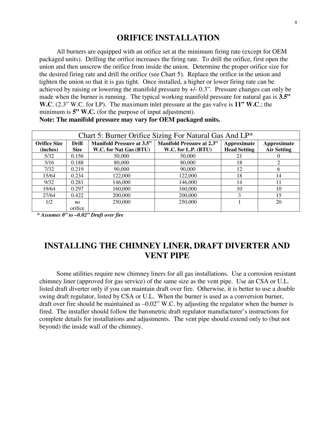
All burners are equipped with an orifice set at the minimum firing rate (except for OEM packaged units). Drilling the orifice increases the firing rate. To drill the orifice, first open the union and then unscrew the orifice from inside the union. Determine the proper orifice size for the desired firing rate and drill the orifice (see Chart 5). Replace the orifice in the union and tighten the union so that it is gas tight. Once installed, a higher or lower firing rate can be achieved by raising or lowering the manifold pressure by +/- 0.3”. Pressure changes can only be made when the burner is running. The typical working manifold pressure for natural gas is 3.5” W.C. (2.3” W.C. for LP). The maximum inlet pressure at the gas valve is 11” W.C.; the minimum is 5” W.C. (for the purpose of input adjustment).
Note: The manifold pressure may vary for OEM packaged units.
Chart 5: Burner Orifice Sizing For Natural Gas And LP*
Orifice Size | Drill | Manifold Pressure at 3.5” | Manifold Pressure at 2.3” | Approximate | Approximate |
(inches) | Size | W.C. for Nat Gas (BTU) | W.C. for L.P. (BTU) | Head Setting | Air Setting |
5/32 | 0.156 | 50,000 | 50,000 | 21 | 0 |
3/16 | 0.188 | 80,000 | 80,000 | 18 | 2 |
7/32 | 0.219 | 90,000 | 90,000 | 12 | 6 |
15/64 | 0.234 | 122,000 | 122,000 | 18 | 14 |
9/32 | 0.281 | 146,000 | 146,000 | 14 | 11 |
19/64 | 0.297 | 160,000 | 160,000 | 10 | 10 |
27/64 | 0.422 | 200,000 | 200,000 | 3 | 15 |
1/2 | no | 250,000 | 250,000 | 1 | 20 |
| orifice |
|
|
|
|
* Assumes 0” to
INSTALLING THE CHIMNEY LINER, DRAFT DIVERTER AND
VENT PIPE
Some utilities require new chimney liners for all gas installations. Use a corrosion resistant chimney liner (approved for gas service) of the same size as the vent pipe. Use an CSA or U.L. listed draft diverter only if you can maintain draft over fire. Otherwise, it is better to use a double swing draft regulator, listed by CSA or U.L. When the burner is used as a conversion burner, draft over fire should be maintained as