11
LIGHTING INSTRUCTIONS
To light the SU-2A Gas Burner
1.Set the thermostat to the lowest temperature
2.The control knob on the gas valve should be in the “OFF” position for at least five minutes.
3.Rotate the control knob counter- clockwise to the “ON” position and set the thermostat to the desired temperature settings
Reset, if Flame Lockout Occurs
1.Turn the thermostat off, or turn the main power off
2.Wait five minutes
3.Turn the main power on
To shut the burner off
1.Rotate the control knob on the gas valve to the “OFF” position
2.Set the thermostat to the lowest temperature
3.Turn Main Power Off.
BURNER OPERATION
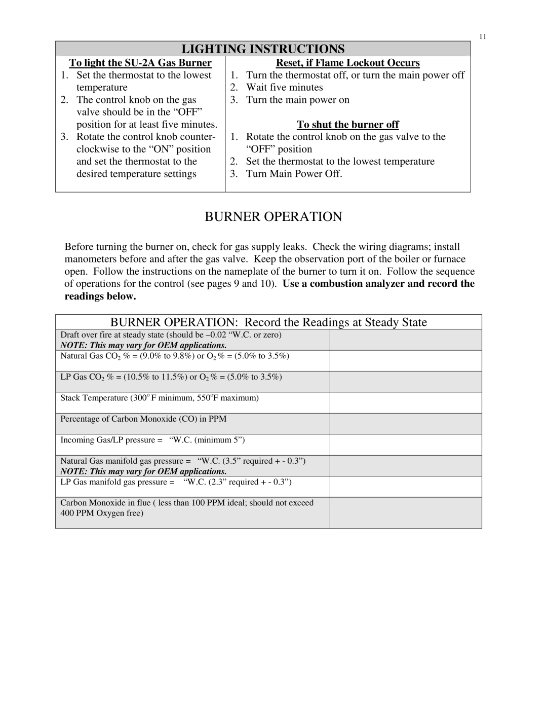
Before turning the burner on, check for gas supply leaks. Check the wiring diagrams; install manometers before and after the gas valve. Keep the observation port of the boiler or furnace open. Follow the instructions on the nameplate of the burner to turn it on. Follow the sequence of operations for the control (see pages 9 and 10). Use a combustion analyzer and record the readings below.
BURNER OPERATION: Record the Readings at Steady State
Draft over fire at steady state (should be
NOTE: This may vary for OEM applications.
Natural Gas CO2 % = (9.0% to 9.8%) or O2 % = (5.0% to 3.5%)
LP Gas CO2 % = (10.5% to 11.5%) or O2 % = (5.0% to 3.5%)
Stack Temperature (300o F minimum, 550oF maximum)
Percentage of Carbon Monoxide (CO) in PPM
Incoming Gas/LP pressure = “W.C. (minimum 5”)
Natural Gas manifold gas pressure = “W.C. (3.5” required + - 0.3”)
NOTE: This may vary for OEM applications.
LP Gas manifold gas pressure = “W.C. (2.3” required + - 0.3”)
Carbon Monoxide in flue ( less than 100 PPM ideal; should not exceed 400 PPM Oxygen free)
