HUAWEI MG323 GSM M2M Module |
|
|
| |||
Hardware Guide |
|
| Description of the Application Interfaces | |||
|
|
|
|
|
|
|
| Pin No. | Signal Name | Description | Feature | Direction |
|
|
|
|
|
|
|
|
| 33 | UART1_TD | DCE receive | The DTE transmits | DTE to DCE |
|
|
|
| data | serial data. |
|
|
|
|
|
|
|
|
|
| 38 | UART1_RING | DCE ring | The DCE notifies | DCE to DTE |
|
|
|
| indicator | the DTE of a |
|
|
|
|
|
| remote call. |
|
|
|
|
|
|
|
|
|
| 32 | UART1_DTR | DCE data | The DTE is ready. | DTE to DCE |
|
|
|
| terminal ready |
|
|
|
|
|
|
|
|
|
|
| 34 | UART1_RTS | DCE request to | The DTE requests | DTE to DCE |
|
|
|
| send | the DCE to send |
|
|
|
|
|
| data. |
|
|
|
|
|
|
|
|
|
| 36 | UART1_DSR | DCE data set | The DCE is ready. | DCE to DTE |
|
|
|
| ready |
|
|
|
|
|
|
|
|
|
|
| 28 | UART1_CTS | DCE clear to | The DCE has | DCE to DTE |
|
|
|
| send | switched to the |
|
|
|
|
|
| data receiving |
|
|
|
|
|
| mode. |
|
|
|
|
|
|
|
|
|
| 24 | UART1_DCD | DCE data | A data link is set | DCE to DTE |
|
|
|
| carrier detect | up. |
|
|
|
|
|
|
|
|
|
3.6.2Circuit Recommended for the UART Interface
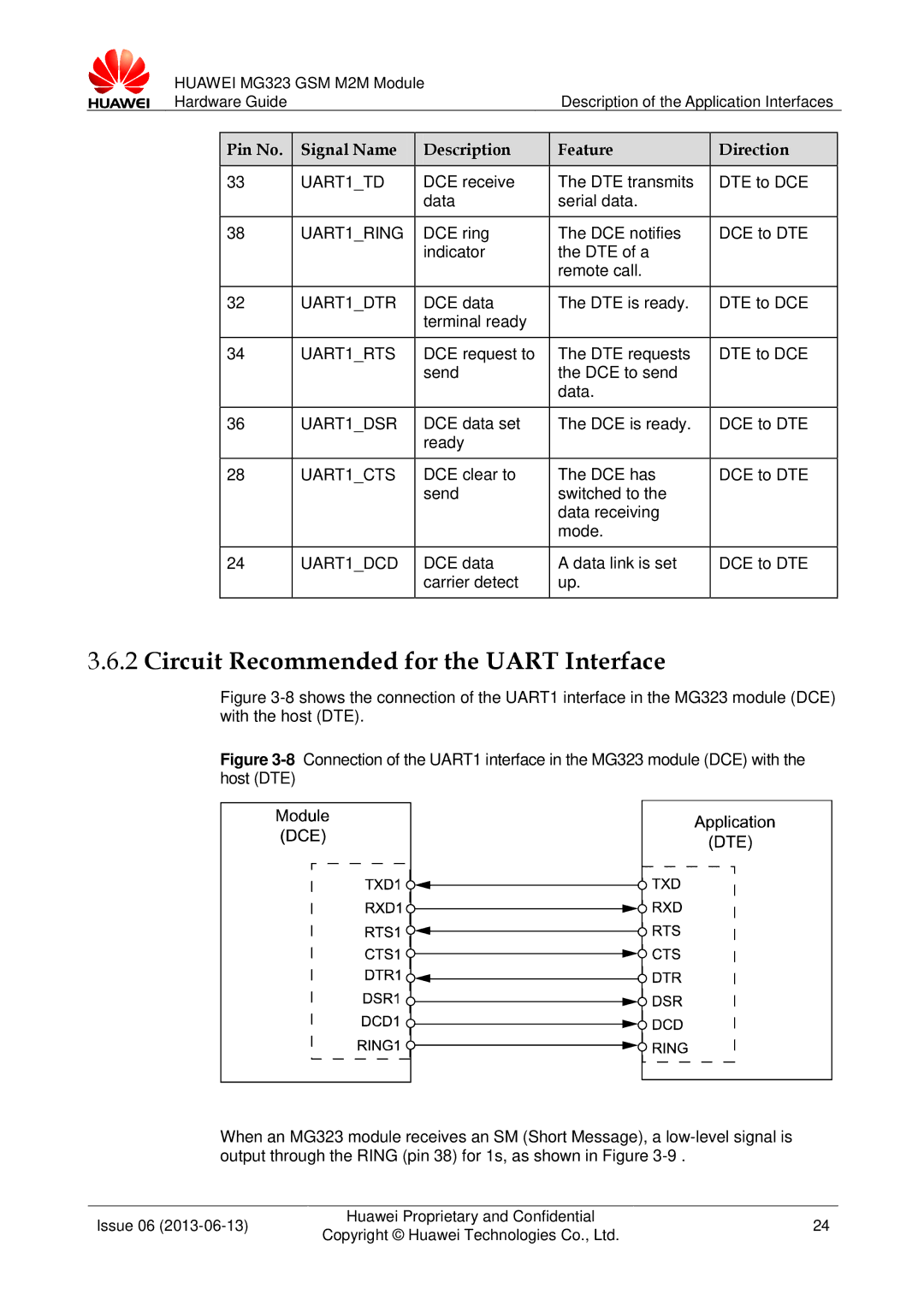
Figure 3-8 shows the connection of the UART1 interface in the MG323 module (DCE) with the host (DTE).
Figure 3-8 Connection of the UART1 interface in the MG323 module (DCE) with the host (DTE)
When an MG323 module receives an SM (Short Message), a low-level signal is output through the RING (pin 38) for 1s, as shown in Figure 3-9 .
Issue 06 | Huawei Proprietary and Confidential | 24 | |
Copyright © Huawei Technologies Co., Ltd. | |||
|
|