HUAWEI MG323 GSM M2M Module |
|
| |||
Hardware Guide |
|
| About This Document | ||
|
|
|
|
|
|
| Version | Date | Chapter | Descriptions |
|
|
|
|
|
|
|
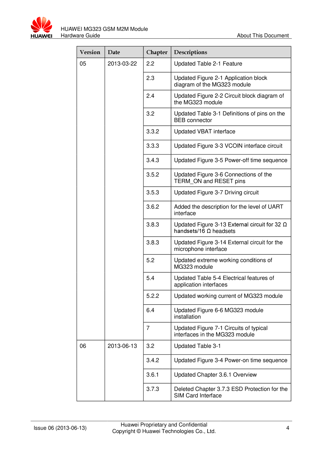
05 | 2.2 | Updated Table | |||
2.3Updated Figure
2.4Updated Figure
3.2Updated Table
3.3.2 | Updated VBAT interface | |
|
|
|
3.3.3 | Updated Figure | VCOIN interface circuit |
|
|
|
3.4.3 | Updated Figure | |
3.5.2Updated Figure
3.5.3Updated Figure
3.6.2Added the description for the level of UART interface
3.8.3Updated Figure
3.8.3Updated Figure
5.2Updated extreme working conditions of MG323 module
5.4Updated Table
5.2.2Updated working current of MG323 module
| 6.4 | Updated Figure | |
|
|
| installation |
|
|
|
|
| 7 | Updated Figure | |
|
|
| interfaces in the MG323 module |
|
|
| |
06 | Updated Table | ||
|
|
|
|
| 3.4.2 | Updated Figure | |
|
|
|
|
| 3.6.1 | Updated Chapter 3.6.1 Overview | |
|
|
|
|
| 3.7.3 | Deleted Chapter 3.7.3 ESD Protection for the | |
|
|
| SIM Card Interface |
Issue 06 | Huawei Proprietary and Confidential | 4 | |
Copyright © Huawei Technologies Co., Ltd. | |||
|
|
