1.Remove the sensor’s cover plate (see Adjustments section).
2.With the circuit(s) on, turn the
3.Push the button(s) to turn the circuit(s) OFF.
4.Push the button(s) again to verify override.
The
ADJUSTMENTS
Open the sensor cover by inserting a small blade screwdriver into the catch at the bottom of the sensor and gently snap the cover loose. Set the adjustment switches as desired (see Configuration Switch Settings below). To
Photocell
The photocell is used to detect if other light sources such as sunlight, are enough to illuminate the space without turning on the lights. For Dual Circuit versions, only Circuit B is controlled by the photocell. The sensor is shipped from the factory with the photocell control disabled. If use of the photocell is desired, calibrate the photocell set points as follows:
1.Remove the sensor’s cover plate.
2.With the sunlight at the desired level where the lights should turn on, press the photocell button.
3.Step back from the sensor to avoid changing ambient light levels in the room. Note: During calibration the sensor will turn the lights off and on.
4.After thecalibration process is complete (approx. 7 min.), reinstall sensor cover. (Calibration is over when LED’s blink in response to motion.)
Switch 1 – Auto/Manual
Controls selection between Auto ON/Auto OFF Mode and Manual ON/Auto OFF Mode. For Dual Circuit versions, this switch controls Auto/Manual Mode for Circuit A only. (Manual ON/Auto off mode requires A button push to turn lights ON.)
Switch 2 – Auto/Manual B (Dual Circuit Versions Only)
Controls selection between Auto ON/Auto OFF Mode and Manual ON/Auto OFF Mode for Circuit B.
Switch 3 – Photocell Mode
Controls selection between One Way Mode and Continuous Mode. In One Way Mode, the sensor turns lights on in response to occupancy when light levels are below the photocell set point then maintains them in the on condition regardless of light level. In Continuous Mode, the sensor functions the same as One Way Mode, except that during periods of occupancy it will turn the lights off if ambient light levels increase sufficiently to illuminate the space. Note: For Dual Circuit versions, the photocell controls the operation of Circuit B only.
Switches 4 and 5 – Timer 1 and Timer 0
Use to set the initial timer value that the sensor will maintain lights on without detecting occupancy. See Auto/Fixed Timer below for additional information.
Switch 6 – Auto/Fixed Timer
Controls selection between Adaptive Timer Mode and Fixed Timer Mode. In Automatic Adaptive Timer Mode, the sensor will use the timer interval setting from switches Timer 0 and Timer 1 above. It will then begin adjusting it’s timer settings as appropriate for the lighted space to optimize performance based on occupancy patterns. In Fixed Timer Mode, the sensor’s
Switch 7 – Hallway
Disables or enables the sensor’s hallway algorithm. When enabled, this feature reduces false tripping of the lights associated with hallway traffi c outside the room where the sensor is controlling the lights. This feature should be enabled when the sensor is installed facing toward the entryway into the room and sensor’s range of detection extends into a hallway or adjoining areas with occupancy.
Switch 8 – Adaptive Reset
When toggled on then off, this switch resets the sensor’s adaptive timer and sensitivity settings. The adaptive timer is reset according to Timer 0 and Timer 1 above. The adaptive sensitivity (both PIR and Ultrasonic as applicable) are reset to factory default. The Photocell Sensor is also reset to factory default (disabled) such that the sensor will turn on the light(s) in response to occupancy regardless of ambient light levels in the lighted space.
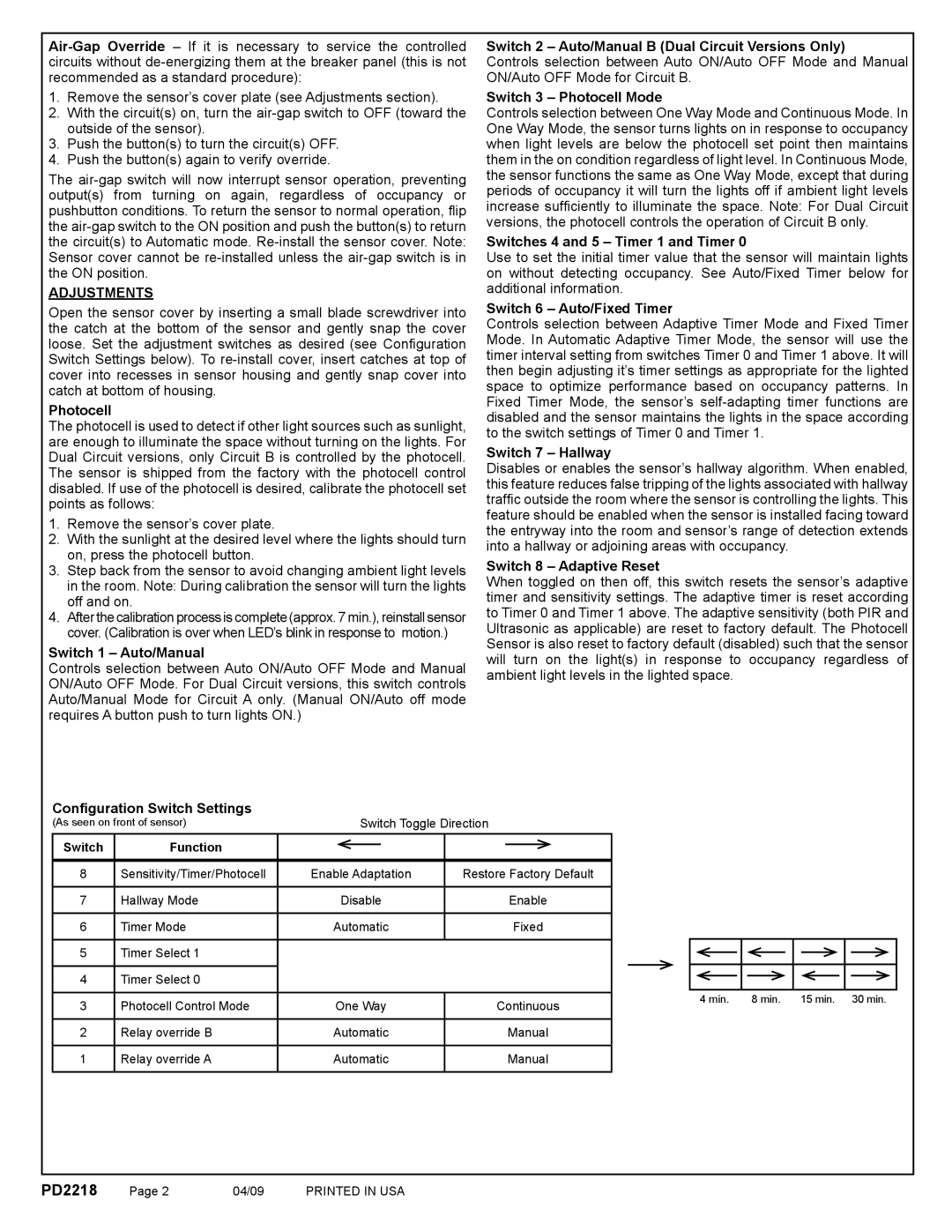
Confi guration Switch Settings
(As seen on front of sensor) |
| Switch Toggle Direction | |||||
Switch | Function |
|
|
|
|
|
|
|
|
|
|
|
| ||
|
|
|
|
|
|
|
|
8 | Sensitivity/Timer/Photocell | Enable Adaptation | Restore Factory Default | ||||
|
|
|
|
|
|
|
|
7 | Hallway Mode |
| Disable |
| Enable | ||
|
|
|
|
|
|
|
|
6 | Timer Mode | Automatic |
| Fixed | |||
|
|
|
|
|
|
|
|
5Timer Select 1
4 Timer Select 0
3 | Photocell Control Mode | One Way | Continuous |
|
|
|
|
2 | Relay override B | Automatic | Manual |
|
|
|
|
1 | Relay override A | Automatic | Manual |
|
|
|
|
4 min. | 8 min. | 15 min. 30 min. |
PD2218 | Page 2 | 04/09 | PRINTED IN USA |