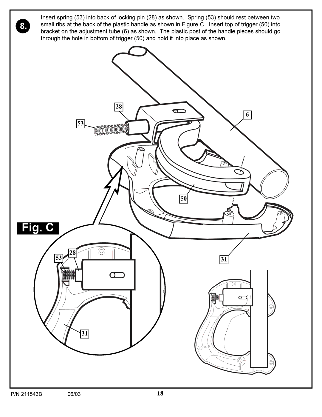
Insert spring (53) into back of locking pin (28) as shown. Spring (53) should rest between two
8. small ribs at the back of the plastic handle as shown in Figure C. Insert top of trigger (50) into bracket on the adjustment tube (6) as shown. The plastic post of the handle pieces should go through the hole in bottom of trigger (50) and hold it into place as shown.
28
53
Fig. C
28
53
6
50
31
![]() 31
31
P/N 211543B | 06/03 | 18 |