TRIAMP MK II - MANUAL
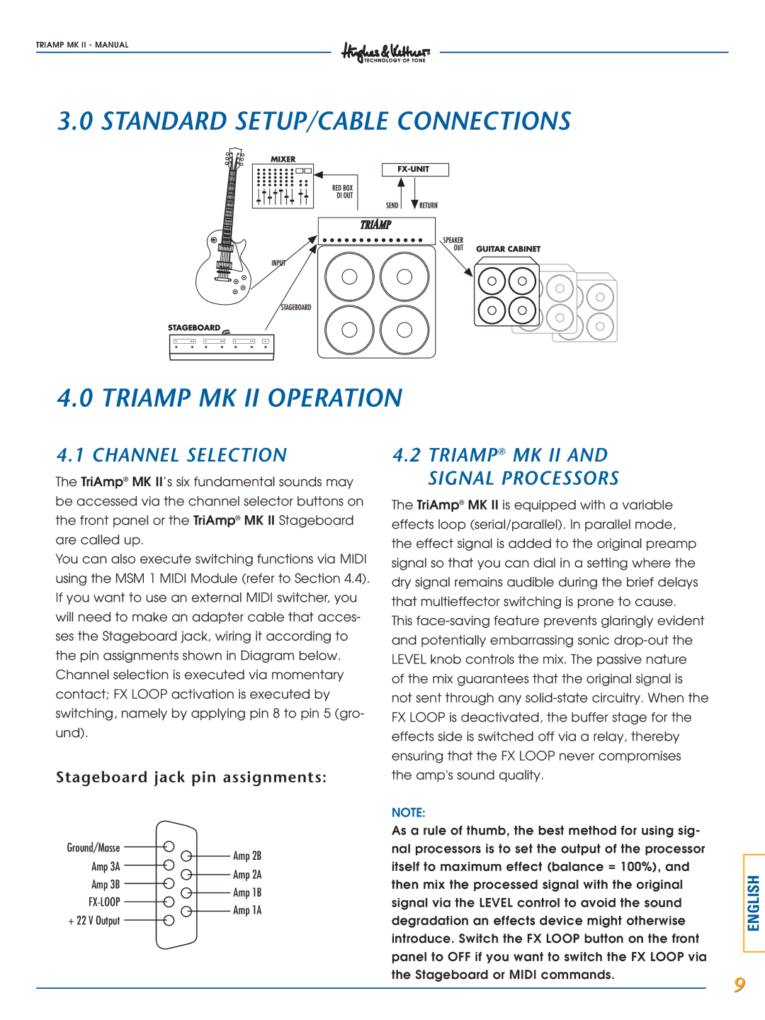
3.0 STANDARD SETUP/CABLE CONNECTIONS
4.0 TRIAMP MK II OPERATION
4.1 CHANNEL SELECTION
The TriAmp® MK II’s six fundamental sounds may be accessed via the channel selector buttons on the front panel or the TriAmp® MK II Stageboard are called up.
You can also execute switching functions via MIDI using the MSM 1 MIDI Module (refer to Section 4.4). If you want to use an external MIDI switcher, you will need to make an adapter cable that acces- ses the Stageboard jack, wiring it according to the pin assignments shown in Diagram below. Channel selection is executed via momentary contact; FX LOOP activation is executed by switching, namely by applying pin 8 to pin 5 (gro- und).
Stageboard jack pin assignments:
4.2TRIAMP® MK II AND SIGNAL PROCESSORS
The TriAmp® MK II is equipped with a variable effects loop (serial/parallel). In parallel mode, the effect signal is added to the original preamp signal so that you can dial in a setting where the dry signal remains audible during the brief delays that multieffector switching is prone to cause.
This
NOTE:
Ground/Masse
Amp 3A
Amp 3B
Amp 2B
Amp 2A
Amp 1B
Amp 1A
As a rule of thumb, the best method for using sig- nal processors is to set the output of the processor itself to maximum effect (balance = 100%), and then mix the processed signal with the original signal via the LEVEL control to avoid the sound
ENGLISH
+ 22 V Output
degradation an effects device might otherwise introduce. Switch the FX LOOP button on the front panel to OFF if you want to switch the FX LOOP via the Stageboard or MIDI commands.
9
