3
Transducer Switch | |
|
NOTE: Use caution while sliding the transducer connectors into the Transducer Switch connectors. The slots for the connectors are keyed to prevent reversed installation, so do not force the connectors together. See your control head installation guide for additional information.
To connect the connector clips to the Transducer Switch:
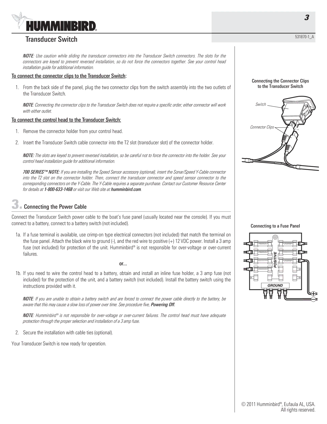
1.From the back side of the panel, plug the two connector clips from the switch assembly into the two outlets of the Transducer Switch.
NOTE: Connecting the connector clips to the Transducer Switch does not require a specific order; either connector will work with either outlet.
To connect the control head to the Transducer Switch:
1.Remove the connector holder from your control head.
2.Insert the Transducer Switch cable connector into the T2 slot (transducer slot) of the connector holder.
NOTE: The slots are keyed to prevent reversed installation, so be careful not to force the connector into the holder. See your control head installation guide for additional information.
700 SERIES™ NOTE: If you are installing the Speed Sensor accessory (optional), insert the Sonar/Speed
3. Connecting the Power Cable
Connect the Transducer Switch power cable to the boat’s fuse panel (usually located near the console). If you must connect to a battery, connect to a battery switch (not included).
1a. If a fuse terminal is available, use
or...
1b. If you need to wire the control head to a battery, obtain and install an inline fuse holder, a 3 amp fuse (not included) for the protection of the unit, and a battery switch (not included). Install the battery switch using the instructions provided with it.
NOTE: If you are unable to obtain a battery switch and are forced to connect the power cable directly to the battery, be aware that this may cause a slow loss of power over time. See procedure five, Powering Off.
NOTE: Humminbird® is not responsible for
2.Secure the installation with cable ties (optional). Your Transducer Switch is now ready for operation.
Connecting the Connector Clips
to the Transducer Switch
Switch
Connector Clips ![]()
![]()
![]()
![]()
![]()
Connecting to a Fuse Panel
© 2011 Humminbird®, Eufaula AL, USA. All rights reserved.