Manuals
/
Humminbird
/
Marine Equipment
/
Fish Finder
Humminbird
947C
manual
Appendix a
Models:
947C
1
90
91
91
Download
91 pages
61.42 Kb
84
85
86
87
88
89
90
91
Troubleshooting
Specification
Install
Chart Menu Tab
Alarms Menu TAB
Restore Defaults
Warranty
Display Problems
View Preset Keys
GPS Diagnostic View
Page 90
Image 90
531374-1_A
- 947 Man.qxd 2/15/2005 7:54 PM Page 90
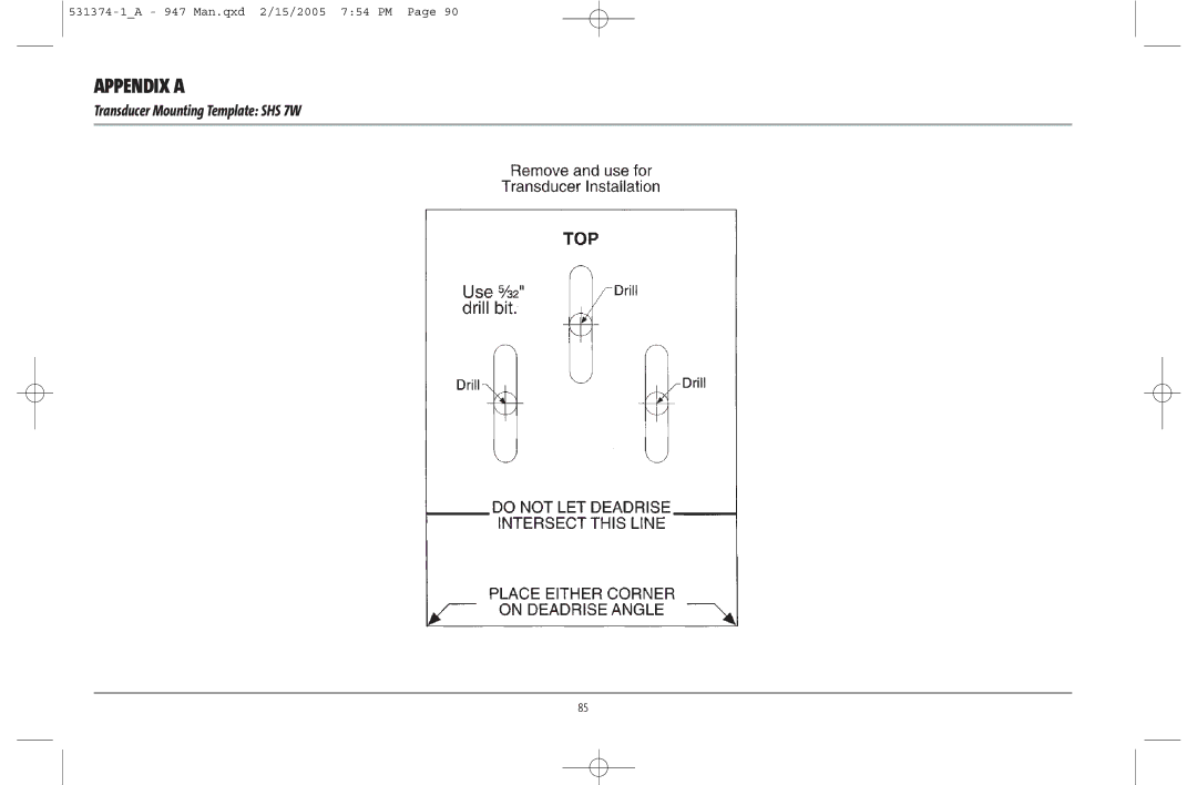
APPENDIX A
Transducer Mounting Template: SHS 7W
85
Page 89
Page 91
Page 90
Image 90
Page 89
Page 91
Contents
531374-1A 947 Man.qxd 2/15/2005 752 PM
Thank You
Table of Contents
3D Sonar X-Press Menu
Menu System Start-Up Options Menu
2D Sonar X-Press Menu
Navigation X-Press Menu
Setup Menu Tab
Chart Menu Tab
Alarms Menu Tab
Views Menu Tab Accessories Menu Tab Troubleshooting
3D Sonar
Series Introduction
HOW the 900 Series Works
2D Sonar
GPS and Cartography
MULTI-MEDIA Card MMC SD Slot
SD Slot
Accessory Bus
Accessory BUS
Installation Overview
900 Series has a wide variety of configurations
Control Head Installation
Basic installation tasks that you must perform include
Gimbal Mounting the Control Head
Mounting Screws Washer Gimbal Mounting Bracket
Cables Routed Near Mounting Bracket
Plug Cable Connector Assembly to Back of Control Head
Screws provided
IN-DASH Mounting the Control Head
Plug Cable Connector Assembly to Back of Control Head
Transducer Installation
Connecting the Control Head Power Cable to the Boat
Transom Transducer Installation
To determine transducer mounting location
Stepped Hull
But do not completely tighten
To mount the transducer bracket to the boat
To attach the pivot to the transducer
Attaching the Bracket
To mount the transducer pivot assembly to the bracket
To adjust the running position of the transducer
Normal Cavitation
Fully tightened
To route the transom transducer cable
Reassemble
Routing the Cable
Inside the Hull Transducer Installation
Trial installation
Determine the transducer mounting location
Make sure the position of the transducer is marked
Permanently mount the transducer
Route the cable
Transducer Mounted Inside the Hull
Test and Finish the Transducer Installation
Trolling Motor Transducer Installation
Hand-tighten only
GPS Receiver Installation
If you have… Then use
Follow these steps to stem mount the GPS receiver
Access Under Mounting Location
Access Under Mounting Location
To the cable as shown
No Access Under Mounting Location
Finish Routing the Cable and Check GPS Receiver Operation
Install the temperature probe accessory
Routing the cable to the control head
Testing the System Installation
To test the installation
Powering UP the Control Head
Series 947c 3D Combo Title Screen
WHAT’S on the 3D Sonar Display
Triplog
WHAT’S on the 2D Sonar Display
Bait Ball RTS Real Time Sonar Window
Real Time Sonar RTS Window
Bottom Presentation
View KEY
POWER/LIGHT KEY
KEY Functions
Menu KEY
Exit KEY
View Preset Keys
WAY Cursor Control KEY
Info KEY
MARK/GOTO KEY
Views
Views available on your 900 Series are
Views and Readouts
3D/2D Combo View
3D/2D Combo View
2D Sonar View
2D Sonar View
2D Zoom View
2D Zoom View
Beam Sonar View
Beam Sonar View
BIRD’S EYE View
Bird’s Eye View
Chart/Bird’s Eye Combo View with Active Cursor
CHART/BIRD’S EYE Combo View
Chart View
Chart View with Active Cursor
CHART/3D Combo View
CHART/2D Combo View
Chart/2D Combo View
Chart Orientation
Chart View with Cursor Present
Viewing Cartography
WAYPOINTS, Routes and Tracks
Navigation
Waypoints, Routes and Tracks
SAVE, EDIT, or Delete a Waypoint
Chart View with Target
Navigate to a Waypoint or Position
ADD a Waypoint Target or Trolling Grid
Chart View with Grid
SAVE, Edit or Delete a Route
Save or Clear a Current Track
EDIT, Delete or Hide Saved Tracks
Menu System
Sonar Tab, Normal Mode
Sonar Tab, Advanced Mode
Normal Operation
Exit Normal operation by powering your 900 Series off
START-UP Options Menu
Start-Up Options Menu
Simulator
Self Test Accessory Test GPS Diagnostic View
Exit the Simulator by powering your 900 Series off
System Status
Accessory Test Screen
Accessory Test
GPS Diagnostic View
GPS Diagnostic View
Active Side
To Adjust Split Screen Position
2D Sonar X-PRESS Menu
Split Position
Sensitivity
To adjust the Sensitivity
To adjust the Upper Range
Upper Range
Chart Speed
Lower Range
Bottom Lock
2D/3D Priority
To adjust the Bottom Range
Bottom Range
To change the 2D/3D Priority
3D Sonar X-PRESS Menu
Highlight Split Position on the 3D Sonar X-Press Menu
3D Sonar X-Press Menu
Beam Sensitivity
3D Bottom Zoom
3D Lower Range
To Reset 3D View
Reset 3D View
To adjust the 3D History
3D History
Highlight Split Position on the Navigation X-Press Menu
Navigation X-Press Menu
Save Current Route
Save Current Track
Clear Current Track
Skip Next Waypoint
Cancel Navigation
Remove Target
Remove Grid
3D Bottom Style
Sonar Menu TAB
2D Sonar Colors
3D Frame Style
To change Beam Select
2D Beam Select
Fish ID+
To set Fish ID+
To change the Fish ID 3D Reference setting
To change the Fish ID Sensitivity setting
To change the RTS Window setting
Fish ID Sensitivity
KHZ Sensitivity
Bottom View
Zoom Width
Depth Lines
Surface Clutter
To change the Noise Filter setting
To change the Max Depth setting
Noise Filter
Temperature Graph
Water Type
Color BAR
Navigation Menu TAB
Tracks
Waypoints
Routes
To change the Chart Orientation setting
To change the North Reference setting
North Reference
Track MIN Distance
Trolling Grid Rotation
Trackpoint Interval
MAP Datum
Delete ALL NAV Data
Chart Menu TAB
Export ALL NAV Data
To Export All Navigation Data
LAT/LON Grid
Chart Detail Level
MAP Borders
Spot Soundings
Shaded Depth
SET MAP Offset
Clear MAP Offset
Fish ID Alarm
Alarms Menu TAB
Depth Alarm
To change the Depth Alarm setting
LOW Battery Alarm
Temp Alarm
OFF Course Alarm
Arrival Alarm
Drift Alarm
Alarm Tone
To change the Units Temp setting
Setup Menu TAB
To change the Units Depth setting
Units Depth
Units Speed
User Mode
Units Distance
Language
Triplog Reset
Restore Defaults
Select Readouts
Default Sonar View Customized Sonar View
To Select Readouts
Local Time Zone
Depth Offset
Temp Offset
Daylight Saving Time
Date Format
Position Format
Time Format
Nmea Output
To turn Nmea Output on or off
Sonar
Views Menu TAB
To turn Sonar on or off
Accessories Menu TAB
Troubleshooting
Series Doesn’t Power Up
Series Defaults to Simulator with a Transducer Attached
Display Problems
Control head loses power at high speeds
Noise re-appears
Finding the Cause of Noise
Other electronic devices
Boat’s engine
Year Limited Warranty
Humminbird Service Policy
Returning Your Unit for Service
Series Accessories
For IN-WARRANTY service, complete the following steps
Specifications
Operating Frequency
Appendix a
Contact Humminbird
Top
Page
Image
Contents