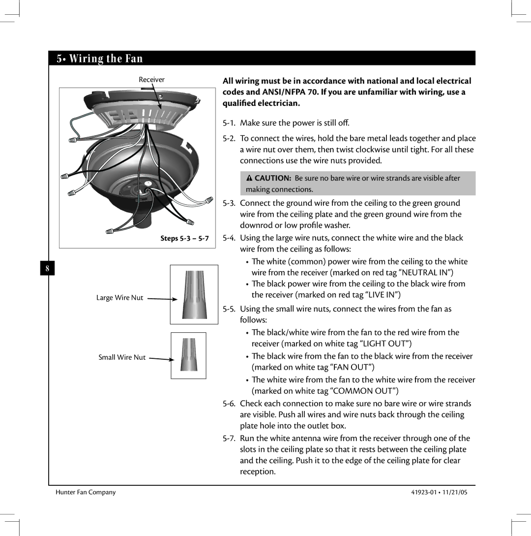
Hunter Fan 41923 warranty Wiring the Fan

Models: 41923

1 14
Download 14 pages 635 b
Page 8
Image 8
5• Wiring the Fan

5• Wiring the Fan

Receiver

Steps 5-35-7

8

Large Wire Nut

Small Wire Nut Manual background

All wiring must be in accordance with national and local electrical codes and ANSI/NFPA 70. If you are unfamiliar with wiring, use a qualified electrician.

5-1. Make sure the power is still off.

5-2. To connect the wires, hold the bare metal leads together and place a wire nut over them, then twist clockwise until tight. For all these connections use the wire nuts provided.

Manual background CAUTION: Be sure no bare wire or wire strands are visible after making connections.

5-3. Connect the ground wire from the ceiling to the green ground wire from the ceiling plate and the green ground wire from the downrod or low profile washer.

5-4. Using the large wire nuts, connect the white wire and the black wire from the ceiling as follows:

e white (common) power wire from the ceiling to the white wire from the receiver (marked on red tag “NEUTRAL IN”)

e black power wire from the ceiling to the black wire from the receiver (marked on red tag “LIVE IN”)

5-5. Using the small wire nuts, connect the wires from the fan as follows:

e black/white wire from the fan to the red wire from the receiver (marked on white tag “LIGHT OUT”)

e black wire from the fan to the black wire from the receiver (marked on white tag “FAN OUT”)

e white wire from the fan to the white wire from the receiver (marked on white tag “COMMON OUT”)

5-6. Check each connection to make sure no bare wire or wire strands are visible. Push all wires and wire nuts back through the ceiling plate hole into the outlet box.

5-7. Run the white antenna wire from the receiver through one of the slots in the ceiling plate so that it rests between the ceiling plate and the ceiling. Push it to the edge of the ceiling plate for clear reception.

Hunter Fan Company

41923-01 • 11/21/05

Page 8
Image 8
Hunter Fan 41923 warranty Wiring the Fan