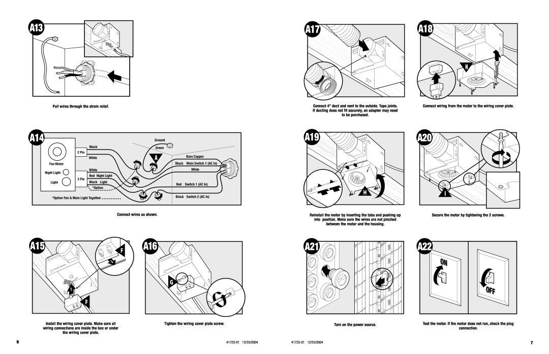
A13 |
Pull wires through the strain relief.
A170 |
Connect 4” duct and vent to the outside. Tape joints. If ducting does not fit securely, an adapter may need to be purchased.
A18 |
H |
Connect wiring from the motor to the wiring cover plate.
A14 |
|
|
| Ground |
|
|
| Black |
| Green |
|
| 2 Pin |
|
| A | Bare Copper |
|
| White |
| ||
|
|
|
| ||
Fan Motor |
|
|
| Black | Main Switch 1 (AC In) |
Night Light |
| White |
|
| White |
| Red Night Light |
|
| ||
| 3 Pin |
|
| ||
Light | Black | Light |
|
| |
| Red | Switch 1 (AC In) | |||
|
| *Option | |||
|
|
|
| ||
*Option Fan & Main Light Together | Black | Switch 2 (AC In) | |||
|
| ||||
Connect wires as shown.
A19 |
H |
Reinstall the motor by inserting the tabs and pushing up
into position. Make sure the wires are not pinched
between the motor and the housing.
A20 |
I |
Secure the motor by tightening the 2 screws.
A15 | F |
| |
| 2 |
| 1 |
| F |
Install the wiring cover plate. Make sure all wiring connections are inside the box or under the wiring cover plate.
6
A16 |
G |
Tighten the wiring cover plate screw.
A21 |
Turn on the power source.
A22
ON
![]()
![]() OFF
OFF
Test the motor. If the motor does not run, check the plug
connection.
7