Page
Page
Contents and Introduction
Symbols and Decals
Symbols and Decals
Symbols and Decals
Symbols and Decals
Location Blade Guard
543 04 57-88SOUND Level 108dBA
Dust Warning
Safety Instructions
General use
California Prop 65 Warning
General Information
Poison Exhaust GAS
Hearing Hazard
Instructions could Result in Death or Serious Bodily Injury
Safety Instructions Safety First
Do not
Page
Is moved
Parts Identification What is What
Blade Arbor Blade H mounts on this surface
Water Tank / Lifting Point Support Holds Water Tank
Parts Identification What is What
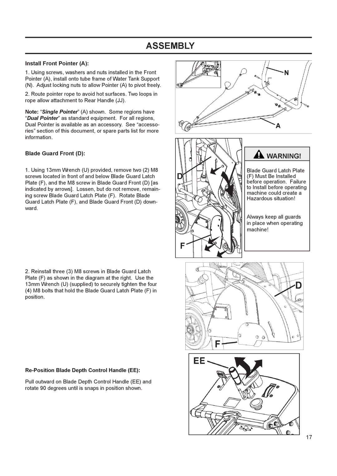
Assembly
Re-Position Blade Depth Control Handle EE
Install Front Pointer a
Blade Guard Front D
Torque Lifting Eye NUT to 83 N-m 61 lb-ft mini Mum
Install Water Tank P if equipped
Assembly
Filling Water Tank
Re-Locating the Blade Guard C If Required
Operation
Before Operation
Parking Machine
Transporting & Lifting Machine
Lifting machine equipped with Water Tank
All Models
Gasoline Engine Models
Fitting the Diamond Blade H
Starting and cutting with machine
Scheduled Maintenance Quick Reference
Maintenance & Lubrication
Service Daily
Service Every 50 Hours
Changing Engine Oil
Engine Oil Checking Engine Oil
2600 3600
Governor Speed
Model Blade Shaft Engine
Engine Will Not Start Cause Action
Trouble Shooting Guide
Wiring Diagram
EMC
Technical Data
HAV
Model Maximum Vibration Aeq in m/s Maximum Exposure Time
Model Nominal Maximum Mass kg 124 158
Cutting Depth
Accessories
26October2006, Olathe, Kansas USA
Conformity Certificates
West 119th Street, Olathe, Kansas 66061 USA
Construction Products, North America Corporate Office
Contact Information
Page
¡ADVERTENCIA
Símbolos y Calcomanías
Símbolos y Calcomanías
Símbolos y Calcomanías
Símbolos y Calcomanías
543 04 57-88SOUND Level 108dBA
Advertencia Sobre EL Polvo
Instrucciones DE Seguridad
Uso general
Advertencia Prop 65 de California
GAS DE Escape Tóxico
Advertencia
Riesgos Auditivos
Información general
LOS SÍ Y LOS no
Instrucciones DE Seguridad ¡LA Seguridad ES LO Primero
Advertencias
Notas
De operación del motor
Identificación DE LAS Piezas QUÉ ES QUÉ
Tanque de agua si se incluye 25 litros
Rote hacia abajo, de manera tal que quede fija hacia adentro
Vuelva a posicionar el manubrio trasero JJ
Ensamblado
Disponga la cuerda del puntero de manera tal que
Instale el puntero delantero a
Protección delantera de la cuchilla D
En su sitio
De accidentes o muerte al levantar la máquina
Instale el tanque de agua P de incluirse
Ensamblado
Llenado del tanque de agua
De control de agua KK
Funcionamiento
Antes de poner en funcionamiento
Izado de la máquina equipada con el tanque de agua
Transporte e izado de la máquina
Estacionamiento de la máquina
Quite la cuchilla H antes del izado, carga o transporte
Todos los modelos
Modelos con motor a gasolina
Colocación de la cuchilla adiamantada H
Presione suavemente el manubrio trasero JJ
Arranque de la máquina y proceso de corte
Levante la sierra hasta la altura máxima. Ahora, con
Referencia Rápida DE Mantenimiento Programado
Mantenimiento Y Lubricación
Servicio Diario
Servicio Cada 50 Horas
Recambio de aceite del motor
Aceite del motor Controle el aceite del motor
Herramientas necesarias
MM mantiene la tensión de la misma
Velocidad del regulador
El exceso de velocidad en la cuchilla adiamantada
El motor no arranca Causa Acción
Guía Para LA Determinación Y Resolución DE Problemas
Diagrama DE Cableado
CEM
Datos Técnicos
VMB
Vibración de mano / brazo
Tor
Modelo Peso nominal Peso máximo 124 158
Modelo RPM del eje de RPM del mo
Accesorios
Certificados DE Cumplimiento
Husqvarna Construction Products, North America Sede Social
Información DE Contacto
Page
Avertissement
Symboles et Autocollants
Symboles et Autocollants
Symboles et Autocollants
Symboles et Autocollants
543 04 57-88SOUND Level 108dBA
Avertissement Concernant LA Poussière
Instructions DE Sécurité
Généralités
Carburant
Information générale
Avertissement
GAZ D’ÉCHAPPEMENT Toxiques
Faire ET À NE PAS Faire
Instructions DE Sécurité Sécurité D’ABORD
Faire
Inhabituelle, NE PAS Utiliser LE Disque
NE PAS Faire
Page
Réservoir d’eau le cas échéant Capacité de
Identification DES Pièces
Identification DES Pièces
Mettre le guidon JJ en position correcte
Assemblage
Avant du protège-disque D
Tirer la manette de commande de profondeur de disque
Poser la flèche avant a
Serrer l’ÉCROU de l’étrier de levage à 83 Nm Lb-ft minimum
Poser le réservoir d’eau P le cas échéant
Assemblage
Remplir le réservoir d’eau
Avant utilisation
Déplacement du protège-disque C Si nécessaire
Utilisation
De ce document
Transport et levage de la machine
Levage d’une machine équipée d’un réservoir d’eau
Stationner la machine
Tous modèles
Tirer le levier OO vers le centre de la machine
Modèles à moteur essence
Pose du disque diamanté H
Démarrer et scier avec la machine
Guide Rapide D’ENTRETIEN Courant
Entretien ET Lubrification
Faire Chaque Jour
Faire Toutes LES 50 Heures
Huile moteur Contrôle de l’huile moteur
Graisseur de la commande de profondeur
Vérifier que le niveau d’huile moteur est correct
Changer l’huile moteur
Outillage nécessaire
La courroie d’entraînement
Serrer au couple indiqué à la figure
Vitesse du régulateur
Le moteur ne démarre pas Cause Action
Guide DE Dépannage
Schéma DE Câblage
Vibrations main-bras
Données Techniques
100
Modèle Masse Masse maximale Nominale kg 124 158
101
Accessoires
Octobre 2006, Olathe, Kansas USA 102
Certificats DE Conformité
Directive 98/37/CE et aux règles régissant sa transposition
103
Informations DE Contact
104