Assembly
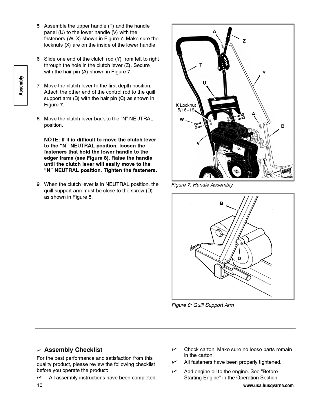
5Assemble the upper handle (T) and the handle panel (U) to the lower handle (V) with the fasteners (W, X) shown in Figure 7. Make sure the locknuts (X) are on the inside of the lower handle.
6Slide one end of the clutch rod (Y) from left to right through the hole in the clutch lever (Z). Secure with the hair pin (A) shown in Figure 7.
7Move the clutch lever to the first depth position. Attach the other end of the control rod to the quill support arm (B) with the hair pin (C) as shown in Figure 7.
8Move the clutch lever back to the “N” NEUTRAL position.
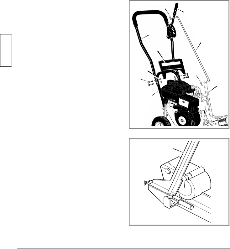
NOTE: If it is difficult to move the clutch lever to the “N” NEUTRAL position, loosen the fasteners that hold the lower handle to the edger frame (see Figure 8). Raise the handle until the clutch lever will easily move to the “N” NEUTRAL position. Tighten the fasteners.
9When the clutch lever is in NEUTRAL position, the quill support arm must be close to the screw (D) as shown in Figure 8.
A
| Z |
| T |
| Y |
| U |
X Locknut |
|
5/16−18 | A |
| |
W |
|
| B |
| V |
Figure 7: Handle Assembly
B
D
Figure 8: Quill Support Arm
nAssembly Checklist
For the best performance and satisfaction from this quality product, please review the following checklist before you operate the product:
nAll assembly instructions have been completed.
10
nCheck carton. Make sure no loose parts remain in the carton.
nAll fasteners have been properly tightened.
nAdd engine oil to the engine. See “Before Starting Engine” in the Operation Section.
www.usa.husqvarna.com