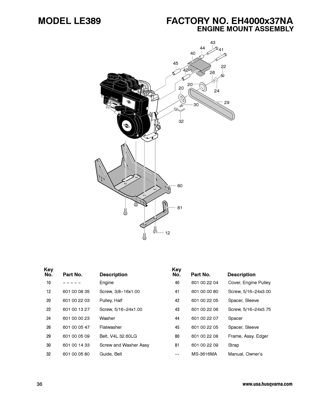
4.2006
PRODUCT INFORMATION
Operator’s Manual − Model LE389
Serial number Engine model
Need Assistance?
Date of purchase Product model number
Features
Safety
Assembly
Maintenance
SYMBOLS ASSOCIATED WITH THIS PRODUCT
Safety
Symbols And Warnings
avoided, will result in death or serious injury
When Operating Equipment
When Adding Fuel
When Starting Engine
When Transporting Equipment
Traumatic amputation or severe laceration can result
Before performing adjustments or repairs
When testing for spark
Severe thermal burns can occur on contact
Operating Safety
Operator Safety Rules Before Use
Fuel Safety
Safe Storage
Repair / Adjustments Safety
Figure 1 Parts Bag Contents
Assembly
Assembly
Parts Packed Separately In Carton
Removal From The Carton
Figure 2 Product Completely Assembled
Figure 4 Right Rear Wheel
How To Assemble The Handle
Figure 3 Lower Handle
Figure 5 Left Rear Wheel
Figure 8 Quill Support Arm
n Assembly Checklist
Figure 7 Handle Assembly
Features
Eye Protection
Operation
Before Starting The Engine
Oil Capacity
High-altitude use
Gasoline Requirements
Type of gasoline to use
Adding Fuel
Figure 11 Clutch / Blade Depth Lever
How To Start The Engine
Figure 12 Engine Controls
Engines give off carbon monoxide, an odorless, colorless, poison gas
Figure 13 Recoil Start
Broken bones, fractures, bruises or sprains could result
Emergency Stopping
How To Stop
How To Use The Throttle Control
Normal Stopping
Figure 16 Clutch / Depth Control Lever
How To Use The Clutch/Depth Control Lever
Thrown debris can cause severe laceration
Traumatic amputation or severe laceration can result
Figure 18 Edging Position
How To Use The Index Lever
Figure 17 Front Wheel Knob
Figure 19 Trimming Position
How To Operate The Edger
Figure 20 Operation Of Edger
Traumatic amputation or severe laceration can result
Curb-hop feature
Figure 21 Curb-Hopping Feature
Rotating parts can contact or entangle
accessories
Edging Tips
hands, feet, hair, clothing, or
Maintenance
Maintenance Chart
Figure 23 Belt Removal
How To Remove The Belt
Figure 22 Clutch / Depth Control Lever
Figure 24 Belt Guard
Sharpening can damage the blade and cause it to break
How To Replace The Blade
Figure 25 Blade Removal
Thrown debris can cause severe laceration
Emission Control
Engine Maintenance
Carburetor Adjustment
Spark Plug
How To Change The Oil
Figure 27 Change Oil
Gasoline and its vapors are extremely flammable and explosive
How To Service The Air Filter
Figure 28 Change Air Filter
Fire or explosion can cause severe burns or death
Engine
Storage
Edger
When Storing Gasoline Or Equipment With Fuel In Tank
CAUSE
Troubleshooting
PROBLEM
CORRECTION
Page
Horsepower
Product Specifications
Power Ratings
Displacement
SECTION 2 HUSQVARNA’S OBLIGATIONS UNDER THE WARRANTY
WARRANTY STATEMENT
SECTION 1 LIMITED WARRANTY
Warranties
SECTION 4 EXCEPTIONS AND LIMITATIONS
SECTION 3 ITEMS NOT COVERED BY THIS WARRANTY
SECTION 6 PROCEDURE TO OBTAIN WARRANTY CONSIDERATION
SECTION 5 CUSTOMER RESPONSIBILITIES
Owner’s Defect Warranty Rights and Obligations
Emissions Control System Warranty Statement
Briggs & Stratton Emissions Control Defects Warranty Coverage
Intermediate
Warranties
Moderate
Extended
FACTORY NO. EH4000x37NA
ENGINE MOUNT ASSEMBLY
MODEL LE389
Description
FACTORY NO. EH4000x37NA
WHEEL ASSEMBLY
MODEL LE389
Description
FACTORY NO. EH4000x37NA
WHEEL BRACKET ASSEMBLY
MODEL LE389
Description
FACTORY NO. EH4000x37NA
CURB-HOP ASSEMBLY
MODEL LE389
Description
FACTORY NO. EH4000x37NA
EDGER BLADE ASSEMBLY
MODEL LE389
Description
FACTORY NO. EH4000x37NA
BLADE GUARD ASSEMBLY
MODEL LE389
Description
FACTORY NO. EH4000x37NA
CLUTCH / DRIVE LEVER ASSEMBLY
MODEL LE389
Description
FACTORY NO. EH4000x37NA
HANDLE ASSEMBLY
MODEL LE389
Description
FACTORY NO. EH4000x37NA
DECALS
MODEL LE389
Description