CONTROLS
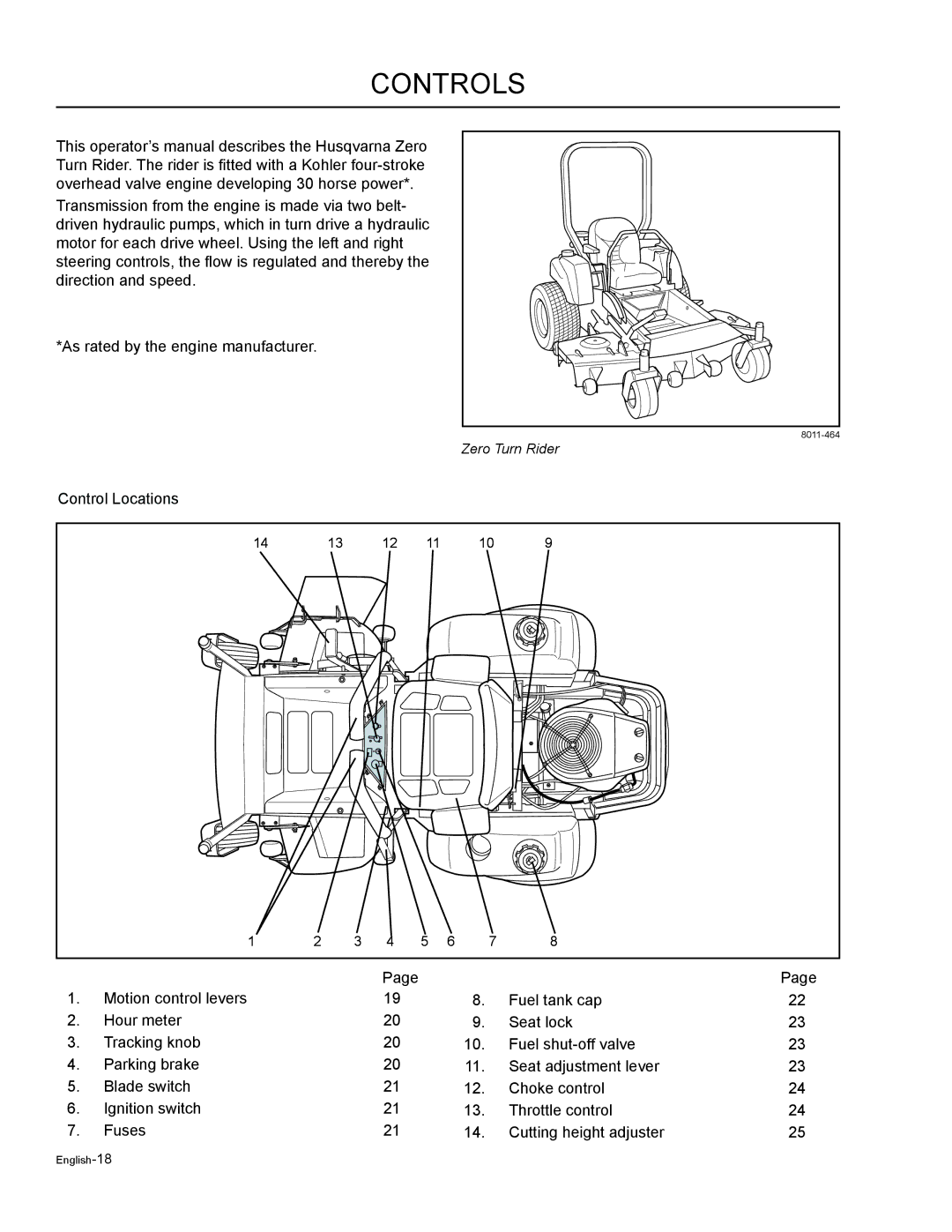
This operator’s manual describes the Husqvarna Zero Turn Rider. The rider is fitted with a Kohler
Transmission from the engine is made via two belt- driven hydraulic pumps, which in turn drive a hydraulic motor for each drive wheel. Using the left and right steering controls, the flow is regulated and thereby the direction and speed.
*As rated by the engine manufacturer.
Zero Turn Rider
Control Locations
14 | 13 | 12 | 11 | 10 | 9 | |
|
|
|
|
|
|
|
|
|
|
|
|
|
|
|
|
|
|
|
|
|
| 1 | 2 | 3 | 4 | 5 | 6 | 7 | 8 |
|
|
|
|
|
|
|
|
|
|
|
|
|
|
| Page |
|
|
|
| Page |
1. | Motion control levers |
|
| 19 |
|
| 8. | Fuel tank cap | 22 |
2. | Hour meter |
|
| 20 |
|
| 9. | Seat lock | 23 |
3. | Tracking knob |
|
| 20 |
|
| 10. | Fuel | 23 |
4. | Parking brake |
|
| 20 |
|
| 11. | Seat adjustment lever | 23 |
5. | Blade switch |
|
| 21 |
|
| 12. | Choke control | 24 |
6. | Ignition switch |
|
| 21 |
|
| 13. | Throttle control | 24 |
7. | Fuses |
|
| 21 |
|
| 14. | Cutting height adjuster | 25 |
