SERVICE AND ADJUSTMENTS
WARNING: TO AVOID SERIOUS INJURY, BEFORE PERFORMING ANY SERVICE OR ADJUST- MENTS:
•Depress brake pedal fully and set parking brake.
•Place attachment clutch in “DISENGAGED” position.
•Turn ignition key to “STOP” and remove key.
•Make sure the blades and all moving parts have completely stopped.
•Disconnect spark plug wire from spark plug and place wire where it cannot come in contact with plug.
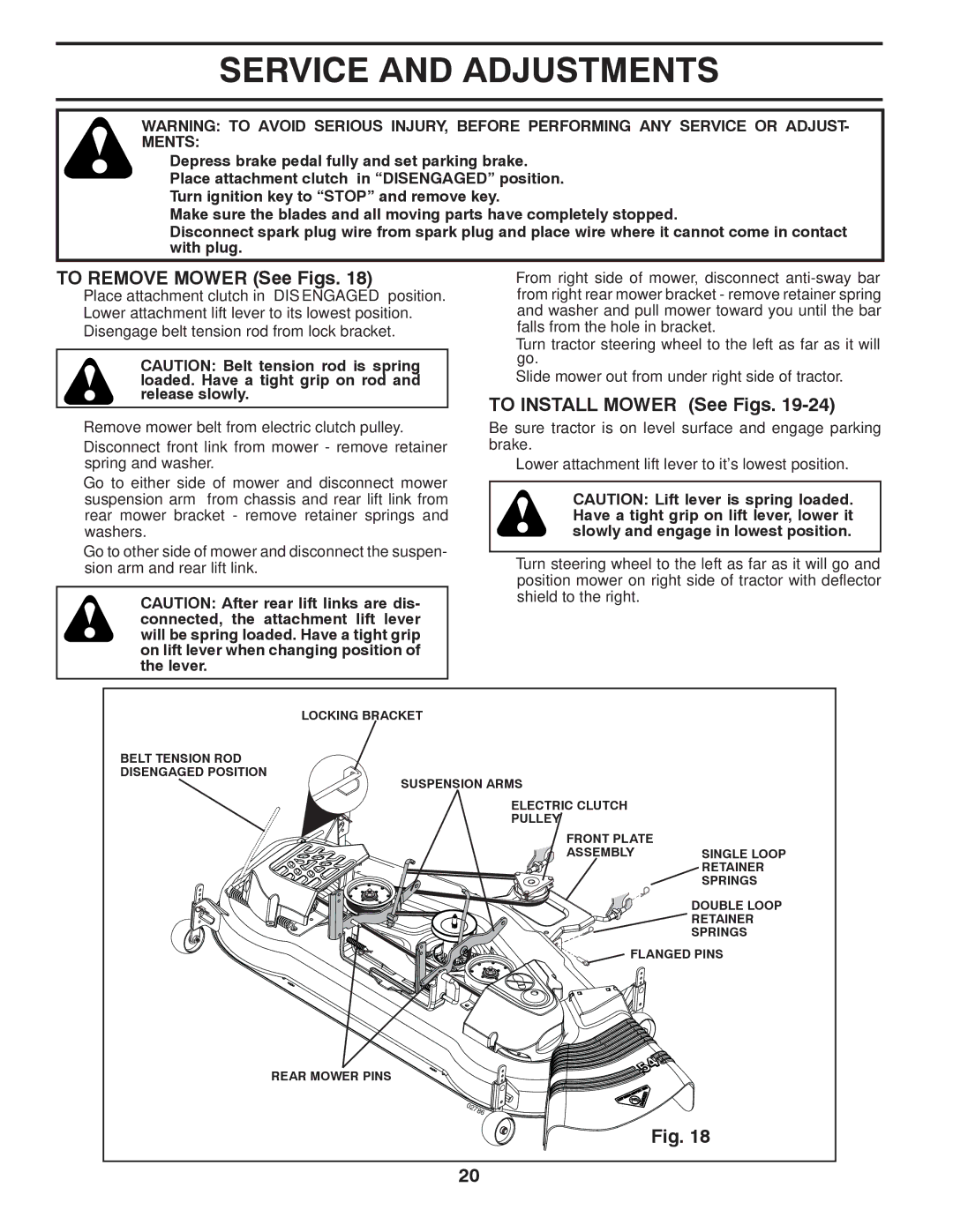
TO REMOVE MOWER (See Figs. 18)
•Place attachment clutch in “DISENGAGED” position.
•Lower attachment lift lever to its lowest position.
•Disengage belt tension rod from lock bracket.
CAUTION: Belt tension rod is spring loaded. Have a tight grip on rod and release slowly.
•From right side of mower, disconnect
•Turn tractor steering wheel to the left as far as it will go.
•Slide mower out from under right side of tractor.
TO INSTALL MOWER (See Figs. 19-24)
•Remove mower belt from electric clutch pulley.
•Disconnect front link from mower - remove retainer spring and washer.
•Go to either side of mower and disconnect mower suspension arm from chassis and rear lift link from rear mower bracket - remove retainer springs and washers.
•Go to other side of mower and disconnect the suspen- sion arm and rear lift link.
CAUTION: After rear lift links are dis- connected, the attachment lift lever will be spring loaded. Have a tight grip on lift lever when changing position of the lever.
Be sure tractor is on level surface and engage parking brake.
•Lower attachment lift lever to it's lowest position.
CAUTION: Lift lever is spring loaded. Have a tight grip on lift lever, lower it slowly and engage in lowest position.
•Turn steering wheel to the left as far as it will go and position mower on right side of tractor with deflector shield to the right.
LOCKING BRACKET
BELT TENSION ROD DISENGAGED POSITION
SUSPENSION ARMS
ELECTRIC CLUTCH
PULLEY
FRONT PLATE
ASSEMBLY SINGLE LOOP RETAINER SPRINGS
DOUBLE LOOP
RETAINER
SPRINGS
FLANGED PINS
REAR MOWER PINS
Fig. 18
20