SERVICE AND ADJUSTMENTS
02965
A
02965
NOTE: Be sure mower side suspension arms (A) are pointing forward before sliding mower under tractor.
•Slide mower under tractor until it is centered under tractor.
•FIRST INSTALL ANTI-SWAY BAR (S).
-From right side of mower, insert
T | S |
| |
A |
|
| 02995 |
FIG. 19
-Pivot bar towards you and insert other end of bar into hole in rear mower bracket (D). Move mower as needed to insert bar.
-Secure with washer and retainer spring as shown
D |
02996 |
FIG. 20
A
B
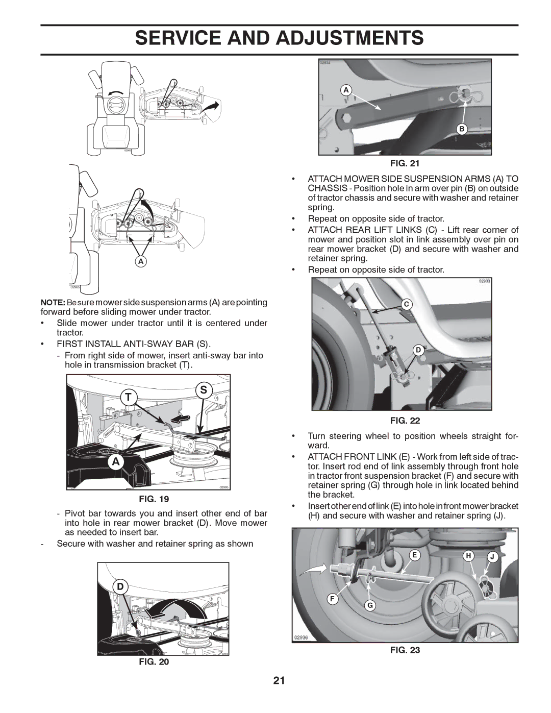
FIG. 21
•ATTACH MOWER SIDE SUSPENSION ARMS (A) TO CHASSIS - Position hole in arm over pin (B) on outside of tractor chassis and secure with washer and retainer spring.
•Repeat on opposite side of tractor.
•ATTACH REAR LIFT LINKS (C) - Lift rear corner of mower and position slot in link assembly over pin on rear mower bracket (D) and secure with washer and retainer spring.
•Repeat on opposite side of tractor.
C
D
FIG. 22
•Turn steering wheel to position wheels straight for- ward.
•ATTACH FRONT LINK (E) - Work from left side of trac- tor. Insert rod end of link assembly through front hole in tractor front suspension bracket (F) and secure with retainer spring (G) through hole in link located behind the bracket.
•Insert other end of link (E) into hole in front mower bracket
(H) and secure with washer and retainer spring (J).
EH J
F![]()
G
FIG. 23
21