4.Electric PTO clutch switch (Fig.
IMPORTANT: Never engage clutch with engine running at high rpm. Clutch, drive line or attachment could be damaged.
WARNING: Never turn the PTO switch ON unless the PTO shaft is securely connected to a power driven attachment.
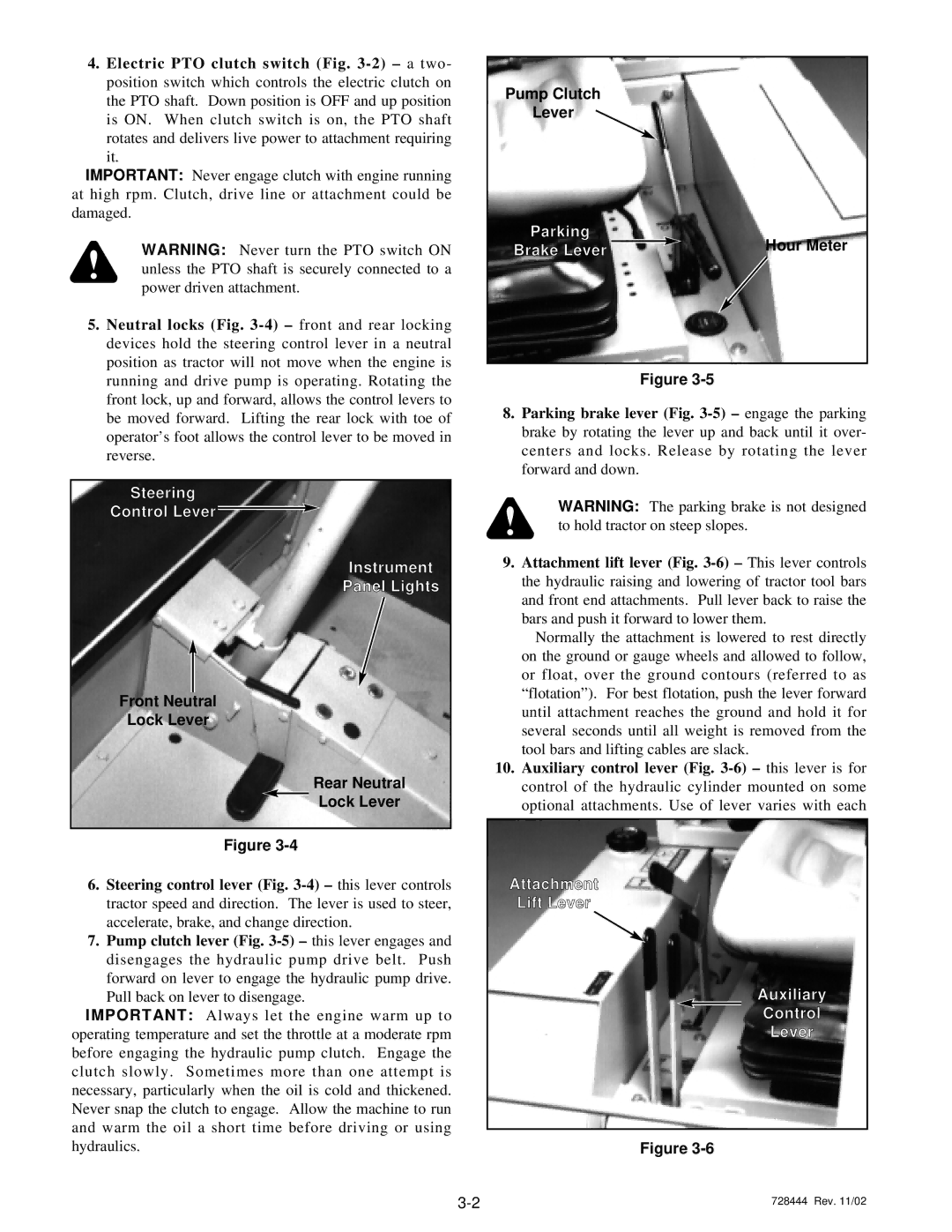
5.Neutral locks (Fig.
Steering
Control Lever ![]()
Instrument
Panel Lights
Front Neutral
Lock Lever
Rear Neutral
Lock Lever
Figure
6.Steering control lever (Fig.
7.Pump clutch lever (Fig.
IMPORTANT: Always let the engine warm up to operating temperature and set the throttle at a moderate rpm before engaging the hydraulic pump clutch. Engage the clutch slowly. Sometimes more than one attempt is necessary, particularly when the oil is cold and thickened. Never snap the clutch to engage. Allow the machine to run and warm the oil a short time before driving or using hydraulics.
Pump Clutch
Lever
Parking |
| Hour Meter |
Brake Lever |
| |
|
|
Figure
8.Parking brake lever (Fig.
WARNING: The parking brake is not designed to hold tractor on steep slopes.
9.Attachment lift lever (Fig.
Normally the attachment is lowered to rest directly on the ground or gauge wheels and allowed to follow, or float, over the ground contours (referred to as “flotation”). For best flotation, push the lever forward until attachment reaches the ground and hold it for several seconds until all weight is removed from the tool bars and lifting cables are slack.
10.Auxiliary control lever (Fig.
Attachment
Lift Lever
Auxiliary
Control
Lever
Figure
728444 Rev. 11/02 |