The Specialist In Drum Handling Equipment
MODEL
Assembly Instructions for Morse Hydra-Lift Drum Karrier Model 400A-60
Serial Number 0604 to ____ (MMYY)
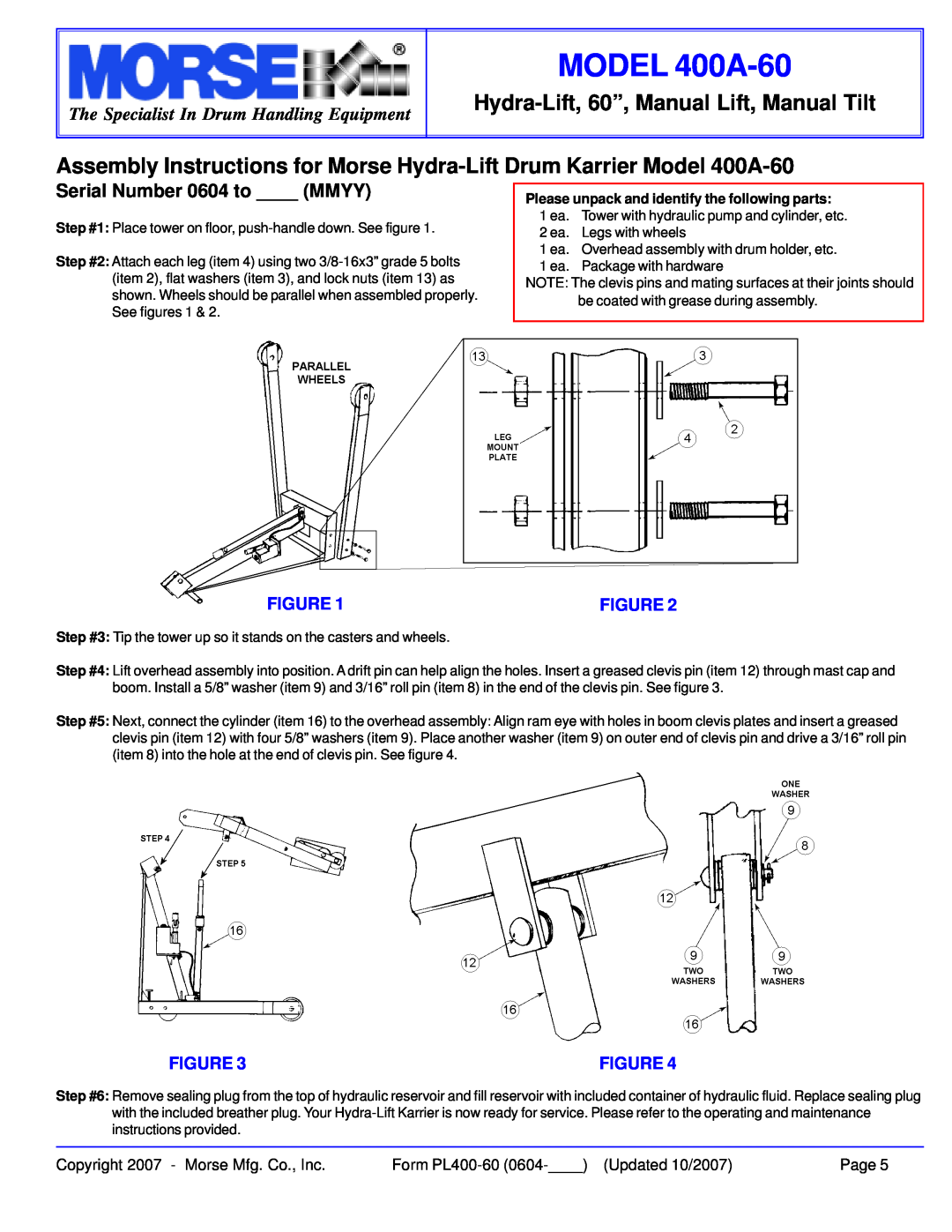
Step #1: Place tower on floor,
Step #2: Attach each leg (item 4) using two
Please unpack and identify the following parts:
1 ea. Tower with hydraulic pump and cylinder, etc.
2 ea. Legs with wheels
1 ea. Overhead assembly with drum holder, etc.
1 ea. Package with hardware
NOTE: The clevis pins and mating surfaces at their joints should be coated with grease during assembly.
FIGURE 1 | FIGURE 2 |
Step #3: Tip the tower up so it stands on the casters and wheels.
Step #4: Lift overhead assembly into position. A drift pin can help align the holes. Insert a greased clevis pin (item 12) through mast cap and boom. Install a 5/8” washer (item 9) and 3/16” roll pin (item 8) in the end of the clevis pin. See figure 3.
Step #5: Next, connect the cylinder (item 16) to the overhead assembly: Align ram eye with holes in boom clevis plates and insert a greased clevis pin (item 12) with four 5/8” washers (item 9). Place another washer (item 9) on outer end of clevis pin and drive a 3/16” roll pin (item 8) into the hole at the end of clevis pin. See figure 4.
FIGURE 3 | FIGURE 4 |
Step #6: Remove sealing plug from the top of hydraulic reservoir and fill reservoir with included container of hydraulic fluid. Replace sealing plug with the included breather plug. Your
Copyright 2007 - Morse Mfg. Co., Inc. | Form | Page 5 |