System Upgrade
There are no system model upgrade conversions available for the 44P Model
170.Processor and memory expansion options are available for this system. The Model 170 is designed for customer setup of the machine and for the subsequent addition of most features (adapters and devices).
Architecture and Technical Information
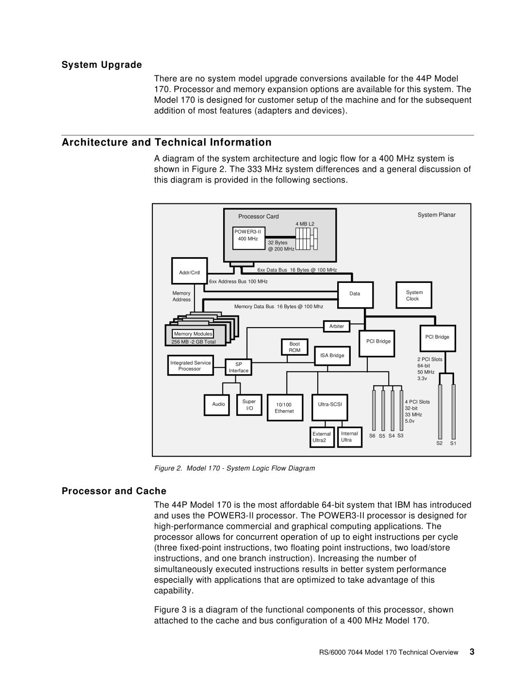
A diagram of the system architecture and logic flow for a 400 MHz system is shown in Figure 2. The 333 MHz system differences and a general discussion of this diagram is provided in the following sections.
Processor Card
4 MB L2
POWER3-II
400 MHz
32 Bytes
@ 200 MHz
Addr/Cntl | 6xx Data Bus 16 Bytes @ 100 MHz |
| |
| 6xx Address Bus 100 MHz |
Memory | Data |
Address |
|
| Memory Data Bus 16 Bytes @ 100 Mhz |
System Planar
System |
Clock |
|
|
| Arbiter |
|
|
|
| |
Memory Modules |
|
|
|
|
|
|
|
|
256 MB |
| Boot |
|
| PCI Bridge |
| ||
|
|
|
|
|
|
|
| |
|
| ROM | ISA Bridge |
|
|
|
| |
|
|
|
|
|
|
| ||
Integrated Service | SP |
|
|
|
|
|
|
|
Processor |
|
|
|
|
|
|
| |
Interface |
|
|
|
|
|
|
| |
|
|
|
|
|
|
|
| |
Audio | Super | 10/100 |
|
|
|
| ||
I/O |
|
|
|
| ||||
| Ethernet |
|
|
|
|
|
| |
|
|
|
|
|
|
|
| |
|
|
| External | Internal | S6 | S5 | S4 | S3 |
|
|
| Ultra2 | Ultra | ||||
|
|
|
|
|
|
| ||
PCI Bridge |
2 PCI Slots
50MHz 3.3v
4 PCI Slots
33MHz 5.0v
S2 S1
Figure 2. Model 170 - System Logic Flow Diagram
Processor and Cache
The 44P Model 170 is the most affordable
