Host 1, Host Adapter 1 and 2 | Host 4, Host Adapter 1 and 2 |
Host 1 | Host 4 |
! OUT 2 Gb/s1 Gb/s
2 Gb/s1 Gb/s! | 2 Gb/s1 Gb/s! | 2 Gb/s1 Gb/s! |
OUT | OUT | OUT |
! OUT 2 Gb/s1 Gb/s
! OUT 2 Gb/s1 Gb/s
! OUT 2 Gb/s1 Gb/s
! OUT 2 Gb/s1 Gb/s
IN | IN | IN | IN | IN | IN | IN | IN |
Host 2 | Host 3 |
Host 2, Host Adapter 1 and 2 | Host 3, Host Adapter 1 and 2 |
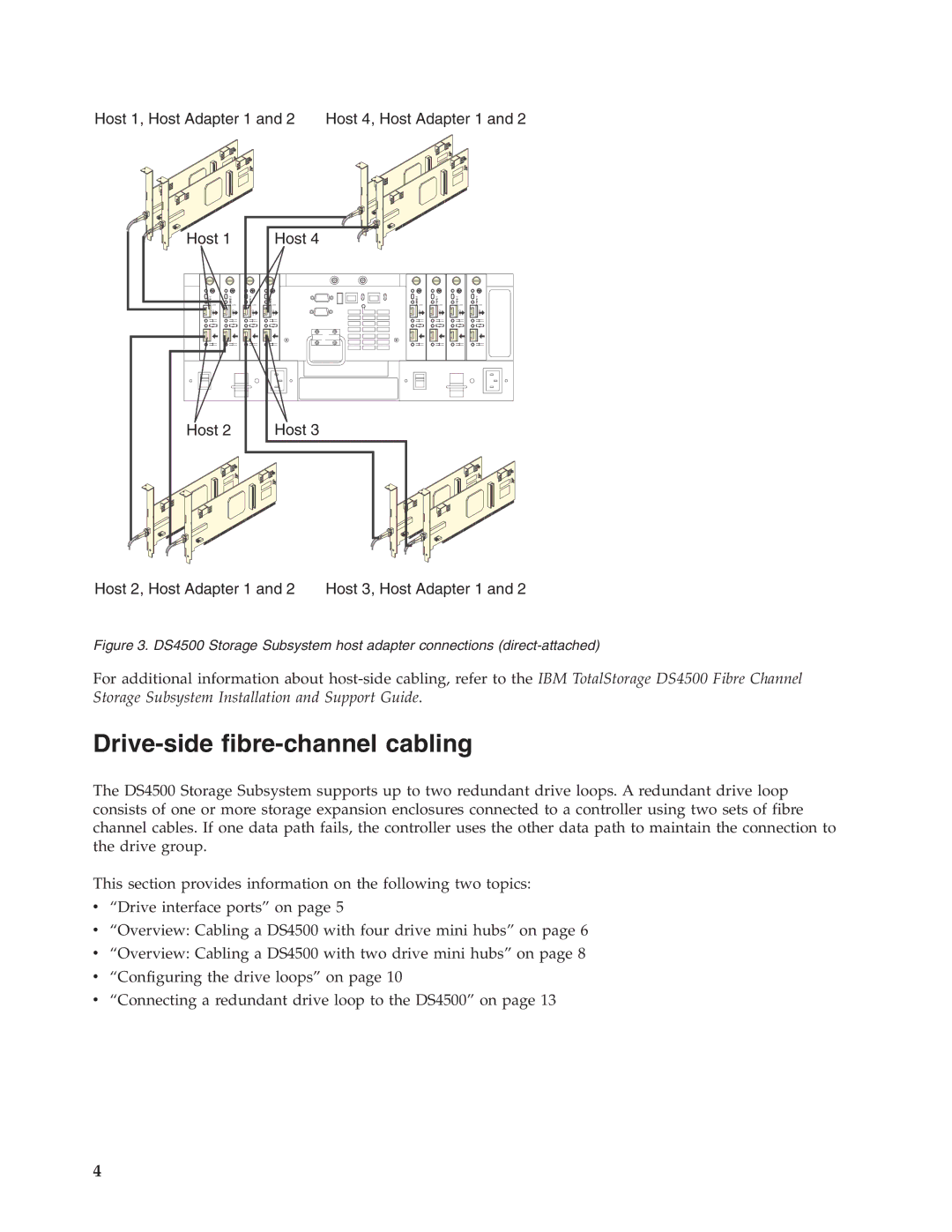
Figure 3. DS4500 Storage Subsystem host adapter connections (direct-attached)
For additional information about
Drive-side fibre-channel cabling
The DS4500 Storage Subsystem supports up to two redundant drive loops. A redundant drive loop consists of one or more storage expansion enclosures connected to a controller using two sets of fibre channel cables. If one data path fails, the controller uses the other data path to maintain the connection to the drive group.
This section provides information on the following two topics:
v“Drive interface ports” on page 5
v“Overview: Cabling a DS4500 with four drive mini hubs” on page 6
v“Overview: Cabling a DS4500 with two drive mini hubs” on page 8
v“Configuring the drive loops” on page 10
v“Connecting a redundant drive loop to the DS4500” on page 13
4
