Loop A Fibre Channel cables
Last storage expansion enclosure
First storage expansion enclosure
Out port on drive mini hub 4
Figure 14. Connecting drive loop A to the DS4500 Storage Subsystem
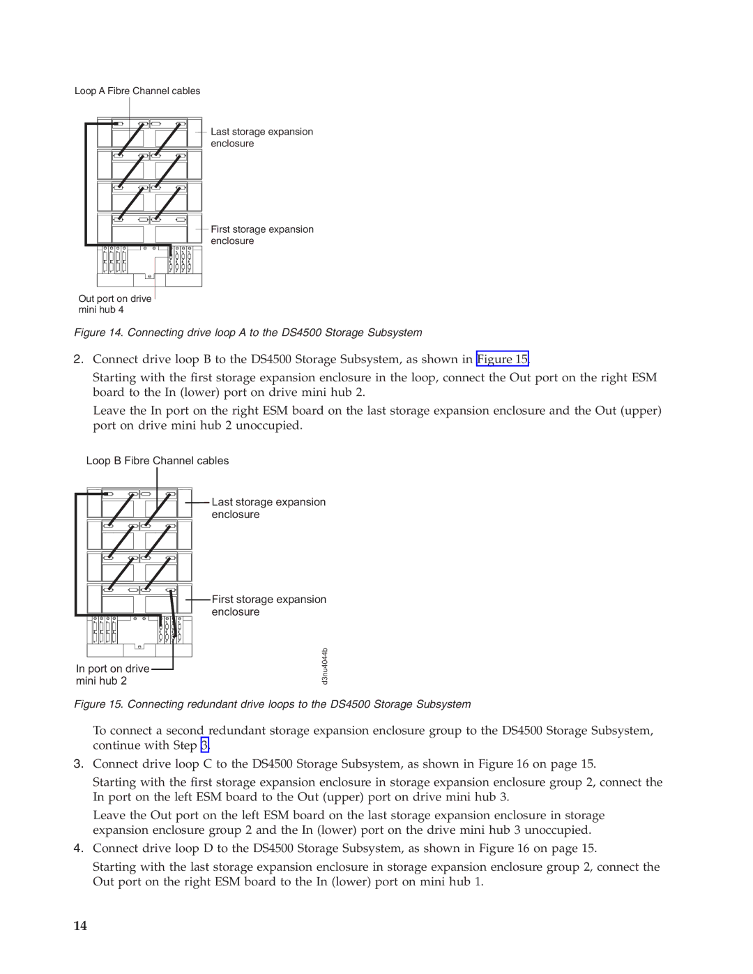
2.Connect drive loop B to the DS4500 Storage Subsystem, as shown in Figure 15.
Starting with the first storage expansion enclosure in the loop, connect the Out port on the right ESM board to the In (lower) port on drive mini hub 2.
Leave the In port on the right ESM board on the last storage expansion enclosure and the Out (upper) port on drive mini hub 2 unoccupied.
Loop B Fibre Channel cables
Last storage expansion enclosure
In port on drive mini hub 2
First storage expansion enclosure
d3nu4044b
Figure 15. Connecting redundant drive loops to the DS4500 Storage Subsystem
To connect a second redundant storage expansion enclosure group to the DS4500 Storage Subsystem, continue with Step 3.
3.Connect drive loop C to the DS4500 Storage Subsystem, as shown in Figure 16 on page 15.
Starting with the first storage expansion enclosure in storage expansion enclosure group 2, connect the In port on the left ESM board to the Out (upper) port on drive mini hub 3.
Leave the Out port on the left ESM board on the last storage expansion enclosure in storage expansion enclosure group 2 and the In (lower) port on the drive mini hub 3 unoccupied.
4.Connect drive loop D to the DS4500 Storage Subsystem, as shown in Figure 16 on page 15.
Starting with the last storage expansion enclosure in storage expansion enclosure group 2, connect the Out port on the right ESM board to the In (lower) port on mini hub 1.
14