swapping these
Attention:
Drive Loop A Fibre | Drive Loop B Fibre | ||
Channel interface | Channel interface | ||
Cables |
| Cables | |
| Input | Output Input | Output |
|
|
|
|
Last DS4000 drive |
enclosure |
Storage Expansion
Enclosures -
Group 1
DS4500 Storage
Subsystem
First DS4000 drive enclosure
Drive Loop A
![]() Drive Loop B
Drive Loop B
|
|
|
|
|
|
|
|
|
|
|
|
|
|
|
|
|
|
|
|
|
|
|
|
|
|
| ds452minb |
|
|
|
|
|
|
|
|
|
|
|
|
|
|
|
|
|
|
|
|
|
|
|
|
|
|
| |
|
|
|
|
|
|
|
|
|
|
|
|
|
|
|
|
|
|
|
|
|
|
|
|
|
|
| |
|
|
|
|
|
|
|
|
|
|
|
|
|
|
|
|
|
|
|
|
|
|
|
|
|
|
| |
|
|
|
|
|
|
|
|
|
|
|
|
|
|
|
|
|
|
|
|
|
|
|
|
|
|
| |
|
|
|
|
|
|
|
|
|
|
|
|
|
|
|
|
|
|
|
|
|
|
|
|
|
|
| |
|
|
|
|
|
|
|
|
|
|
|
|
|
|
|
|
|
|
|
|
|
|
|
|
|
|
| |
|
|
|
|
|
|
|
|
|
|
|
|
|
|
|
|
|
|
|
|
|
|
|
|
|
|
| |
Drive minihub 4 |
|
|
|
| Drive minihub 2 | ||||||||||||||||||||||
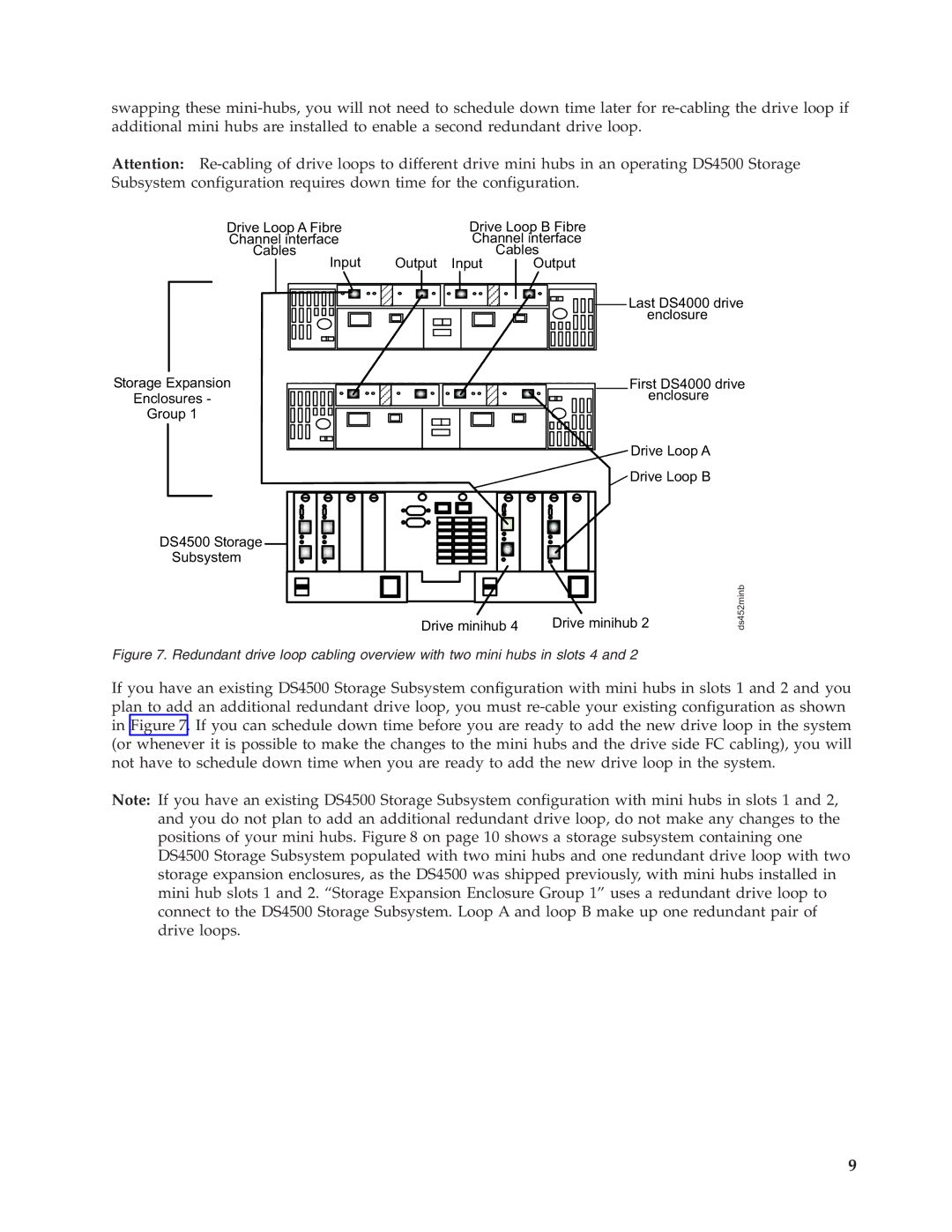
Figure 7. Redundant drive loop cabling overview with two mini hubs in slots 4 and 2
If you have an existing DS4500 Storage Subsystem configuration with mini hubs in slots 1 and 2 and you plan to add an additional redundant drive loop, you must
Note: If you have an existing DS4500 Storage Subsystem configuration with mini hubs in slots 1 and 2, and you do not plan to add an additional redundant drive loop, do not make any changes to the positions of your mini hubs. Figure 8 on page 10 shows a storage subsystem containing one DS4500 Storage Subsystem populated with two mini hubs and one redundant drive loop with two storage expansion enclosures, as the DS4500 was shipped previously, with mini hubs installed in mini hub slots 1 and 2. “Storage Expansion Enclosure Group 1” uses a redundant drive loop to connect to the DS4500 Storage Subsystem. Loop A and loop B make up one redundant pair of drive loops.
9