Contents
ETX-DB-ATX
2. Installation
ETX-DB-ATX
ETX MODULE BASEBOARD PCB Manual Revision
1 Introduction
1.1 Specifications Display interface
3ETX-DB-ATX
2.1 ETX-DB-ATX Board Layout
2 Installation
1.2 What You Have
2.4 Clear CMOS Setup
2.2 Unpacking Precautions
Clear CMOS Setup
7ETX-DB-ATX
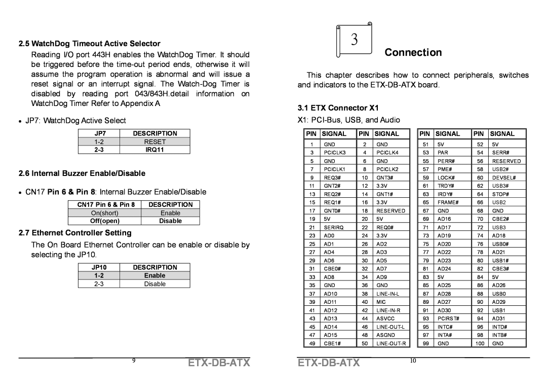
3.1 ETX Connector
2.5 WatchDog Timeout Active Selector
2.6 Internal Buzzer Enable/Disable
2.7 Ethernet Controller Setting
X3 VGA, LCD, Video, COM1, COM2, LPT/Floppy, Irda, Mouse, and Keyboard
3.3 ETX Connector
3.2 ETX Connector X2 X2 ISA Bus
3.5 Floppy Disk Drive Connector
3.4 ETX Connector
CN4 FDC CONNECTOR
X4 IDE1, IDE2, and Miscellaneous
15ETX-DB-ATX
3.6 PCI E-IDE Disk Drive Connector
3.7 Parallel Port
3.8 Serial Ports
3.10 IrDA Infrared Interface Port
3.9 USB Port Connector
3.12 VGA Connector
CN12 Two channel 48 bits LVDS Interface Connector
3.13 LCD/LVDS Interface Connector
3.14 LAN RJ45 Connector
19ETX-DB-ATX
PSLOT1~PSLOT2 PCI Bus pin assignment
21ETX-DB-ATX
3.17 ISA BUS Interface
ISA1 ISA Bus pin assignment
3.20 Digital IO connector CN1 Digital IO connector pin assignment
3.18 ATX power connector PW1 ATX power connector pin assignment
3.21 Keyboard & PS/2 Mouse Connector
23ETX-DB-ATX