Product introduction |
|
This network connection LED is on when the 4810/4910 is connected to a | |
hub or switch. |
| This LED blinks during receive/send transmission. |
|
|
| Rear connectors |
See the rear connector for your 4810/4910 model: | |
v Go to “Rear connectors 4810 (31x models).” | |
v Go to “Rear connectors 32x models” on page | |
Rear connectors 4810 (31x models) | |
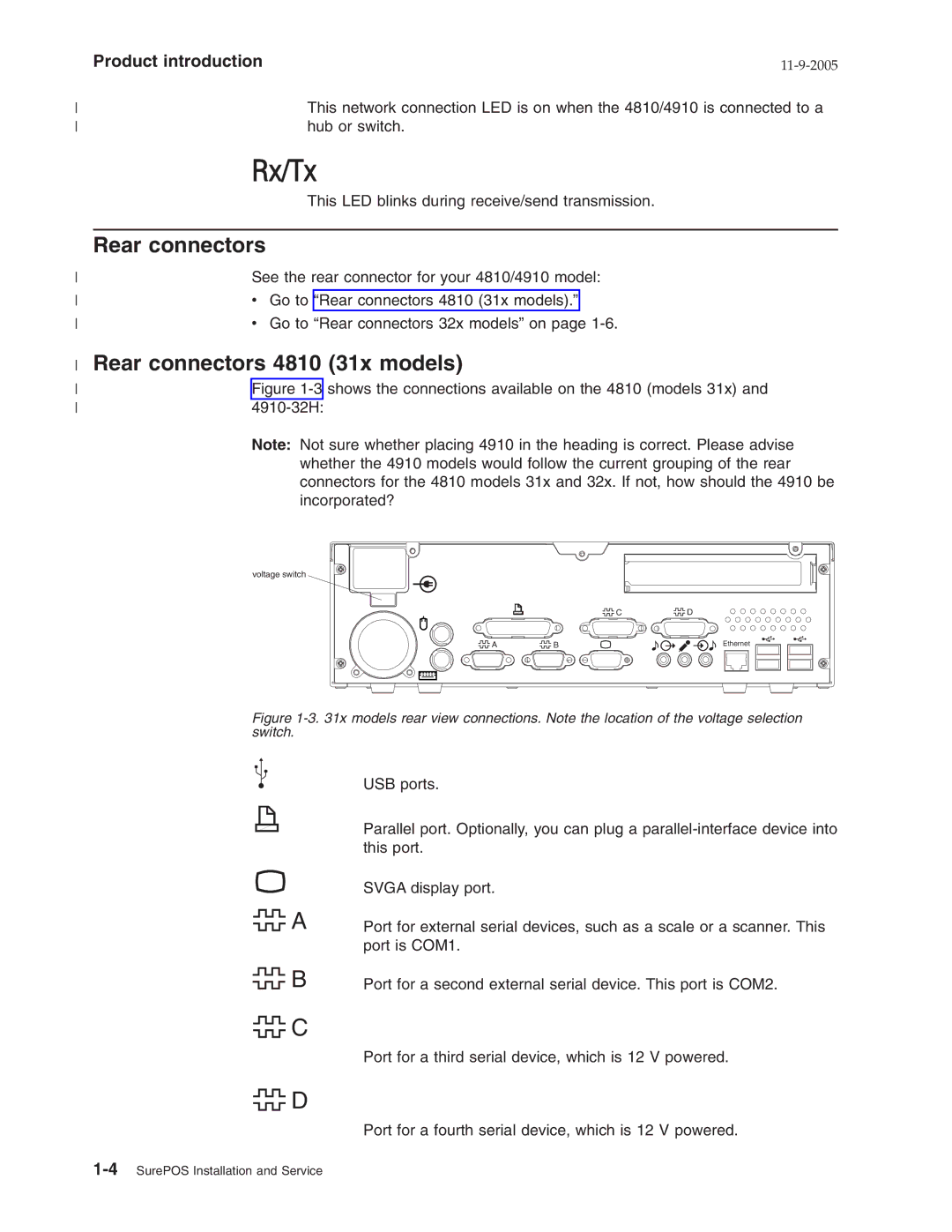
Figure | |
| Note: Not sure whether placing 4910 in the heading is correct. Please advise |
| whether the 4910 models would follow the current grouping of the rear |
| connectors for the 4810 models 31x and 32x. If not, how should the 4910 be |
| incorporated? |
voltage switch
| C | D |
A | B | Ethernet |
Figure 1-3. 31x models rear view connections. Note the location of the voltage selection switch.
![]() A
A
![]() B
B
![]() C
C
![]() D
D
USB ports.
Parallel port. Optionally, you can plug a
SVGA display port.
Port for external serial devices, such as a scale or a scanner. This port is COM1.
Port for a second external serial device. This port is COM2.
Port for a third serial device, which is 12 V powered.
Port for a fourth serial device, which is 12 V powered.