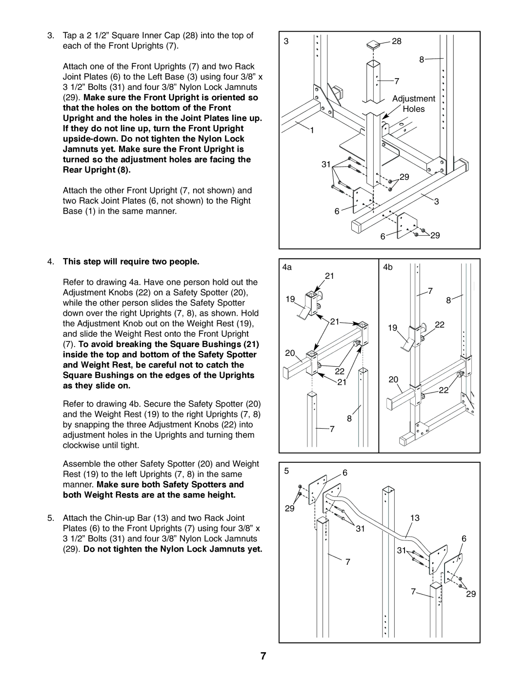
3.Tap a 2 1/2” Square Inner Cap (28) into the top of each of the Front Uprights (7).
Attach one of the Front Uprights (7) and two Rack Joint Plates (6) to the Left Base (3) using four 3/8” x 3 1/2” Bolts (31) and four 3/8” Nylon Lock Jamnuts (29). Make sure the Front Upright is oriented so that the holes on the bottom of the Front Upright and the holes in the Joint Plates line up. If they do not line up, turn the Front Upright
Attach the other Front Upright (7, not shown) and two Rack Joint Plates (6, not shown) to the Right Base (1) in the same manner.
4.This step will require two people.
Refer to drawing 4a. Have one person hold out the Adjustment Knobs (22) on a Safety Spotter (20), while the other person slides the Safety Spotter down over the right Uprights (7, 8), as shown. Hold the Adjustment Knob out on the Weight Rest (19), and slide the Weight Rest onto the Front Upright
(7). To avoid breaking the Square Bushings (21) inside the top and bottom of the Safety Spotter and Weight Rest, be careful not to catch the Square Bushings on the edges of the Uprights as they slide on.
Refer to drawing 4b. Secure the Safety Spotter (20) and the Weight Rest (19) to the right Uprights (7, 8) by snapping the three Adjustment Knobs (22) into adjustment holes in the Uprights and turning them clockwise until tight.
Assemble the other Safety Spotter (20) and Weight Rest (19) to the left Uprights (7, 8) in the same manner. Make sure both Safety Spotters and both Weight Rests are at the same height.
5.Attach the
3 | 28 |
8
7
Adjustment
![]() Holes
Holes ![]()
| 1 |
|
|
| 31 |
|
|
|
| 29 |
|
| 6 |
| 3 |
|
|
| |
|
| 6 | 29 |
4a | 21 | 4b |
|
|
|
| |
19 |
|
| 7 |
|
| 8 | |
| 21 | 19 | 22 |
|
| ||
|
|
| |
20 |
|
|
|
| 22 | 20 |
|
| 21 |
| |
|
| 22 | |
|
|
| |
| 8 |
|
|
| 7 |
|
|
5 | 6 |
|
|
29 |
| 13 |
|
|
|
| |
|
| 31 | 6 |
|
|
| |
|
| 31 |
|
| 7 |
|
|
|
| 7 | 29 |
7