in the spa. Allow the water to circulate for five min- utes. You should now test the pH level of the water. Use the included test strips to check the pH of the water. Refer to the instructions on the test strip pack- aging to see how to use the test strips.
If the level is too low, add one teaspoon from one of the ÒQUICK pHix It UPÓ packets to the water. Let the water circulate through the spa jet unit for five min- utes. Test the pH level again. Repeat until the pH level is correct.
If the level is too high, add one teaspoon from the ÒQUICK pHix It DOWNÓ packets to the water. Let the water circulate through the spa jet unit for five min- utes. Test the pH level again. Repeat until the pH level is correct.
Replace the spa cover and allow the water to contin- ue to heat.
See WATER CHEMISTRY on page 13 for information concerning proper water maintenance.
THE HEATING SYSTEM OF YOUR SPA
The heating system in your spa is designed to be economical for
|
|
|
|
|
|
| Air Temperature |
|
| Heating Time |
|
| At least 70¡F |
|
| 20 to 28 hours |
|
| At least 50¡F |
|
| 28 to 48 hours |
|
| At least 30¡F |
|
| 48 to 72 hours |
|
|
|
|
|
|
|
|
|
|
|
|
|
|
|
|
|
|
|
SECURING THE SPA COVER |
|
| |||
turn. To unlock the buckles, insert the key and turn it counterclockwise a quarter turn.
Always keep the buckles locked when the spa is not in use. Keep the keys in a safe place, out of the reach of children.
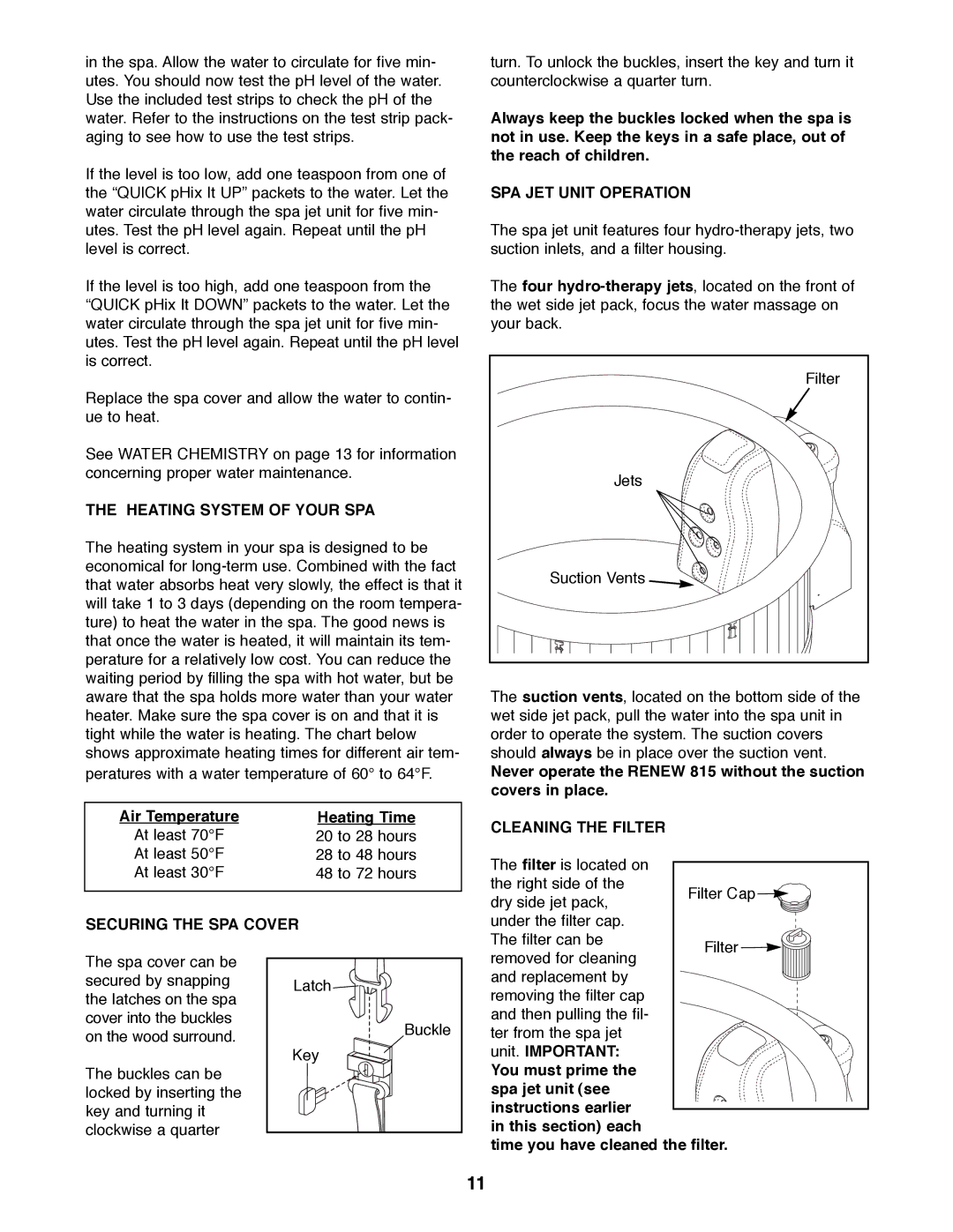
SPA JET UNIT OPERATION
The spa jet unit features four
The four
Filter
Jets
Suction Vents ![]()
The suction vents, located on the bottom side of the wet side jet pack, pull the water into the spa unit in order to operate the system. The suction covers should always be in place over the suction vent.
Never operate the RENEW 815 without the suction covers in place.
CLEANING THE FILTER
The filter is located on |
|
|
|
|
|
| |
the right side of the |
|
|
|
| Filter Cap |
| |
dry side jet pack, |
|
| |
|
|
| |
under the filter cap. |
|
|
|
The filter can be |
| Filter | |
|
| ||
The spa cover can be secured by snapping the latches on the spa cover into the buckles on the wood surround.
The buckles can be locked by inserting the key and turning it clockwise a quarter
Latch
Buckle
Key
removed for cleaning |
and replacement by |
removing the filter cap |
and then pulling the fil- |
ter from the spa jet |
unit. IMPORTANT: |
You must prime the |
spa jet unit (see |
instructions earlier |
in this section) each |
time you have cleaned the filter.
11