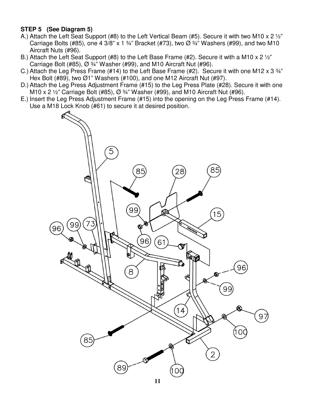
STEP 5 (See Diagram 5)
A.) Attach the Left Seat Support (#8) to the Left Vertical Beam (#5). Secure it with two M10 x 2 ½” Carriage Bolts (#85), one 4 3/8” x 1 ¾” Bracket (#73), two Ø ¾” Washers (#99), and two M10 Aircraft Nuts (#96).
B.) Attach the Left Seat Support (#8) to the Left Base Frame (#2). Secure it with a M10 x 2 ½” Carriage Bolt (#85), Ø ¾” Washer (#99), and M10 Aircraft Nut (#96).
C.) Attach the Leg Press Frame (#14) to the Left Base Frame (#2). Secure it with one M12 x 3 ¾” Hex Bolt (#89), two Ø1” Washers (#100), and one M12 Aircraft Nut (#97).
D.) Attach the Leg Press Adjustment Frame (#15) to the Leg Press Plate (#28). Secure it with one M10 x 2 ½” Carriage Bolt (#85), Ø ¾” Washer (#99), and M10 Aircraft Nut (#96).
E.) Insert the Leg Press Adjustment Frame (#15) into the opening on the Leg Press Frame (#14). Use a M18 Lock Knob (#61) to secure it at desired position.
11