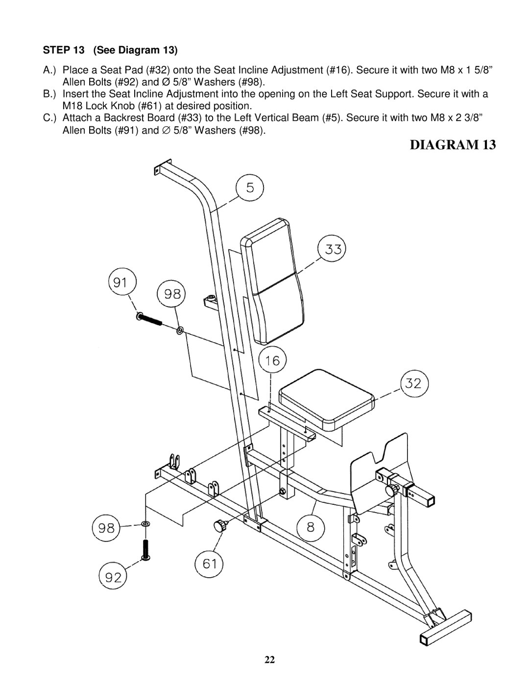
STEP 13 (See Diagram 13)
A.) | Place a Seat Pad (#32) onto the Seat Incline Adjustment (#16). Secure it with two M8 x 1 5/8” |
| Allen Bolts (#92) and Ø 5/8” Washers (#98). |
B.) | Insert the Seat Incline Adjustment into the opening on the Left Seat Support. Secure it with a |
| M18 Lock Knob (#61) at desired position. |
C.) | Attach a Backrest Board (#33) to the Left Vertical Beam (#5). Secure it with two M8 x 2 3/8” |
| Allen Bolts (#91) and ∅ 5/8” Washers (#98). |
| DIAGRAM 13 |
22
