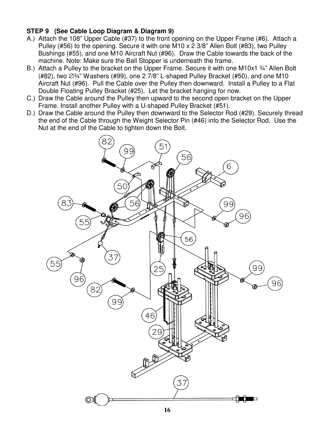
STEP 9 (See Cable Loop Diagram & Diagram 9)
A.) Attach the 108” Upper Cable (#37) to the front opening on the Upper Frame (#6). Attach a Pulley (#56) to the opening. Secure it with one M10 x 2 3/8” Allen Bolt (#83), two Pulley Bushings (#55), and one M10 Aircraft Nut (#96). Draw the Cable towards the back of the machine. Note: Make sure the Ball Stopper is underneath the frame.
B.) Attach a Pulley to the bracket on the Upper Frame. Secure it with one M10x1 ¾” Allen Bolt (#82), two ∅ ¾” Washers (#99), one 2 7/8”
C.) Draw the Cable around the Pulley then upward to the second open bracket on the Upper Frame. Install another Pulley with a
D.) Draw the Cable around the Pulley then downward to the Selector Rod (#29). Securely thread the end of the Cable through the Weight Selector Pin (#46) into the Selector Rod. Use the Nut at the end of the Cable to tighten down the Bolt.
16