ASSEMBLY INSTRUCTION
Tools Required for Assembling the Machine: Two Adjustable Wrenches and Allen
Wrenches. NOTE: It is strongly recommended that two or more people assemble this machine to avoid possible injury.
STEP 1 (See Diagram 1)
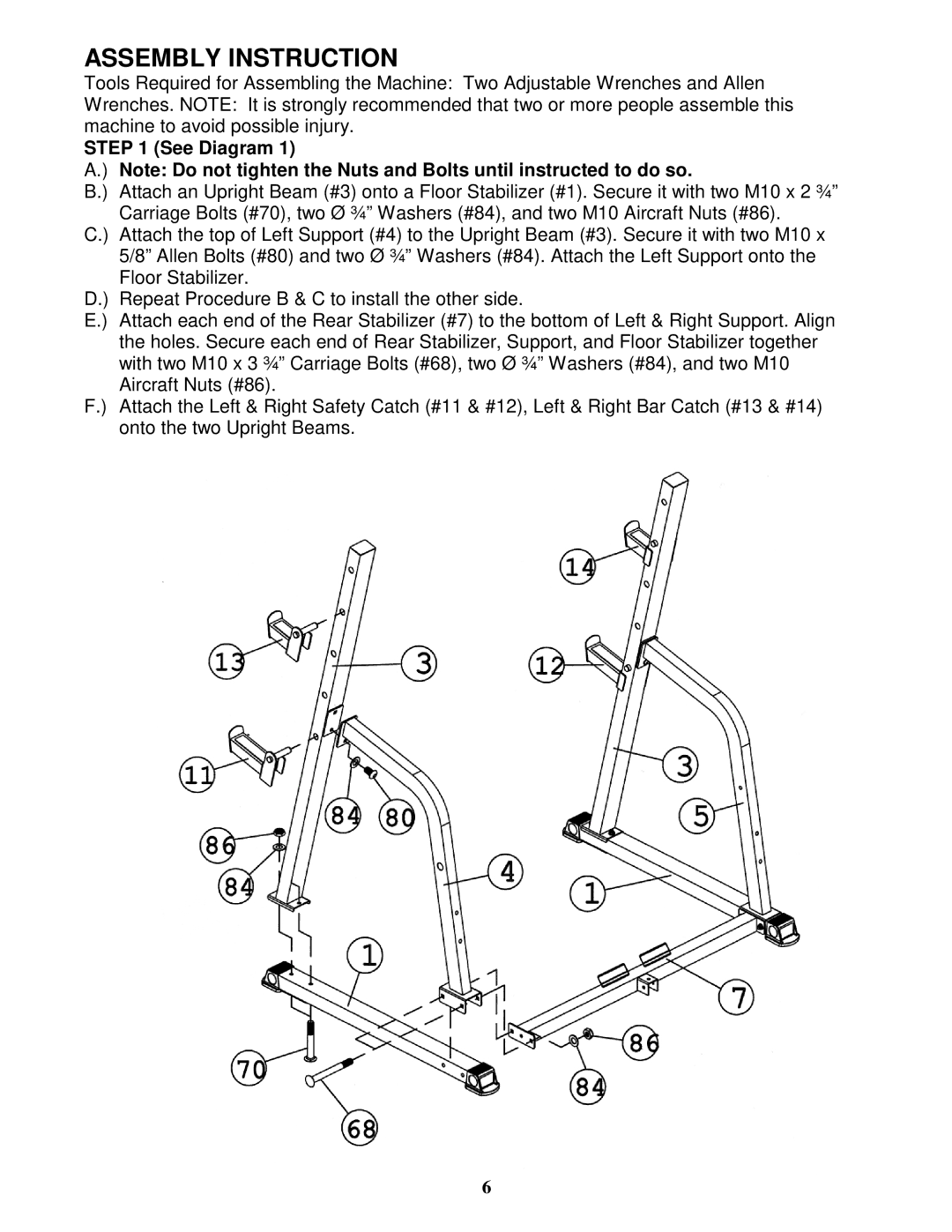
A.) Note: Do not tighten the Nuts and Bolts until instructed to do so.
B.) Attach an Upright Beam (#3) onto a Floor Stabilizer (#1). Secure it with two M10 x 2 ¾” Carriage Bolts (#70), two Ø ¾” Washers (#84), and two M10 Aircraft Nuts (#86).
C.) Attach the top of Left Support (#4) to the Upright Beam (#3). Secure it with two M10 x 5/8” Allen Bolts (#80) and two Ø ¾” Washers (#84). Attach the Left Support onto the Floor Stabilizer.
D.) Repeat Procedure B & C to install the other side.
E.) Attach each end of the Rear Stabilizer (#7) to the bottom of Left & Right Support. Align the holes. Secure each end of Rear Stabilizer, Support, and Floor Stabilizer together with two M10 x 3 ¾” Carriage Bolts (#68), two Ø ¾” Washers (#84), and two M10 Aircraft Nuts (#86).
F.) Attach the Left & Right Safety Catch (#11 & #12), Left & Right Bar Catch (#13 & #14) onto the two Upright Beams.
6