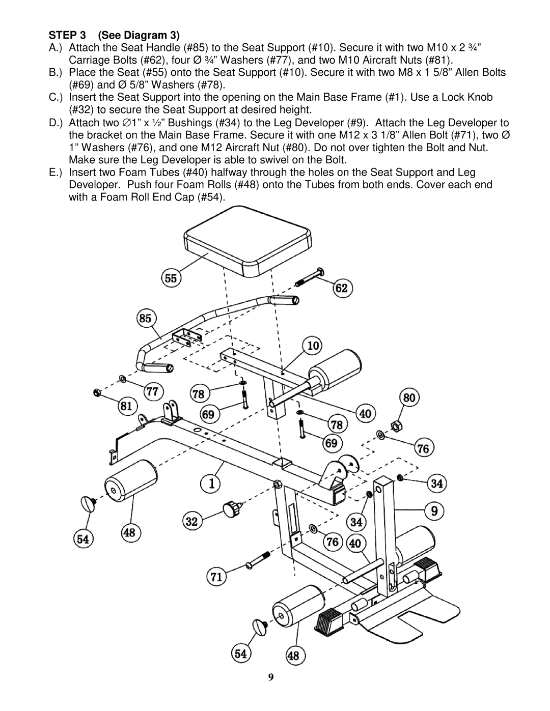
STEP 3 (See Diagram 3)
A.) Attach the Seat Handle (#85) to the Seat Support (#10). Secure it with two M10 x 2 ¾” Carriage Bolts (#62), four Ø ¾” Washers (#77), and two M10 Aircraft Nuts (#81).
B.) Place the Seat (#55) onto the Seat Support (#10). Secure it with two M8 x 1 5/8” Allen Bolts (#69) and Ø 5/8” Washers (#78).
C.) Insert the Seat Support into the opening on the Main Base Frame (#1). Use a Lock Knob (#32) to secure the Seat Support at desired height.
D.) Attach two ∅ 1” x ½” Bushings (#34) to the Leg Developer (#9). Attach the Leg Developer to the bracket on the Main Base Frame. Secure it with one M12 x 3 1/8” Allen Bolt (#71), two Ø 1” Washers (#76), and one M12 Aircraft Nut (#80). Do not over tighten the Bolt and Nut.
Make sure the Leg Developer is able to swivel on the Bolt.
E.) Insert two Foam Tubes (#40) halfway through the holes on the Seat Support and Leg Developer. Push four Foam Rolls (#48) onto the Tubes from both ends. Cover each end with a Foam Roll End Cap (#54).
9