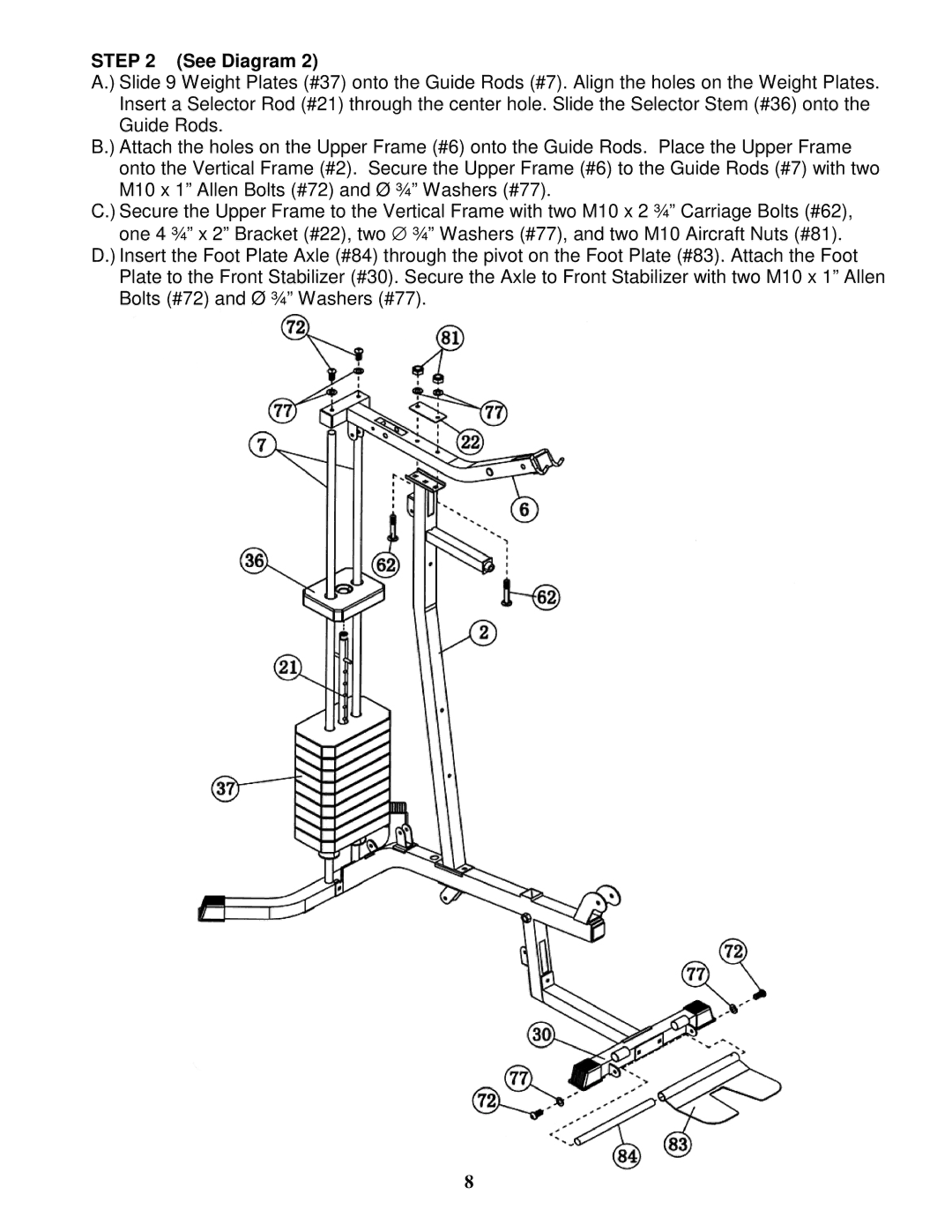
STEP 2 (See Diagram 2)
A.) Slide 9 Weight Plates (#37) onto the Guide Rods (#7). Align the holes on the Weight Plates. Insert a Selector Rod (#21) through the center hole. Slide the Selector Stem (#36) onto the Guide Rods.
B.) Attach the holes on the Upper Frame (#6) onto the Guide Rods. Place the Upper Frame onto the Vertical Frame (#2). Secure the Upper Frame (#6) to the Guide Rods (#7) with two M10 x 1” Allen Bolts (#72) and Ø ¾” Washers (#77).
C.) Secure the Upper Frame to the Vertical Frame with two M10 x 2 ¾” Carriage Bolts (#62), one 4 ¾” x 2” Bracket (#22), two ∅ ¾” Washers (#77), and two M10 Aircraft Nuts (#81).
D.) Insert the Foot Plate Axle (#84) through the pivot on the Foot Plate (#83). Attach the Foot Plate to the Front Stabilizer (#30). Secure the Axle to Front Stabilizer with two M10 x 1” Allen Bolts (#72) and Ø ¾” Washers (#77).
8