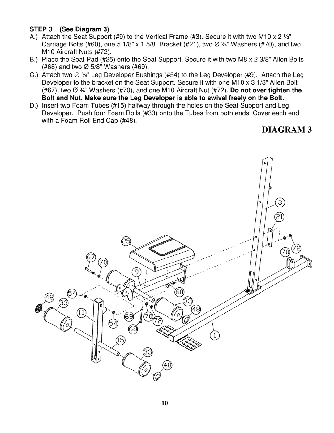
STEP 3 (See Diagram 3)
A.) Attach the Seat Support (#9) to the Vertical Frame (#3). Secure it with two M10 x 2 ½” Carriage Bolts (#60), one 5 1/8” x 1 5/8” Bracket (#21), two Ø ¾” Washers (#70), and two M10 Aircraft Nuts (#72).
B.) Place the Seat Pad (#25) onto the Seat Support. Secure it with two M8 x 2 3/8” Allen Bolts (#68) and two Ø 5/8” Washers (#69).
C.) Attach two ∅ ¾” Leg Developer Bushings (#54) to the Leg Developer (#9). Attach the Leg Developer to the bracket on the Seat Support. Secure it with one M10 x 3 1/8” Allen Bolt (#67), two Ø ¾” Washers (#70), and one M10 Aircraft Nut (#72). Do not over tighten the
Bolt and Nut. Make sure the Leg Developer is able to swivel freely on the Bolt. D.) Insert two Foam Tubes (#15) halfway through the holes on the Seat Support and Leg
Developer. Push four Foam Rolls (#33) onto the Tubes from both ends. Cover each end with a Foam Roll End Cap (#48).
DIAGRAM 3
10