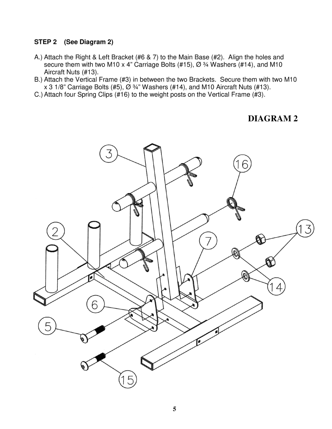
STEP 2 (See Diagram 2)
A.) Attach the Right & Left Bracket (#6 & 7) to the Main Base (#2). Align the holes and secure them with two M10 x 4” Carriage Bolts (#15), Ø ¾ Washers (#14), and M10 Aircraft Nuts (#13).
B.) Attach the Vertical Frame (#3) in between the two Brackets. Secure them with two M10 x 3 1/8” Carriage Bolts (#5), Ø ¾” Washers (#14), and M10 Aircraft Nuts (#13).
C.) Attach four Spring Clips (#16) to the weight posts on the Vertical Frame (#3).
DIAGRAM 2
5