STEP 3 (See Diagram 3)
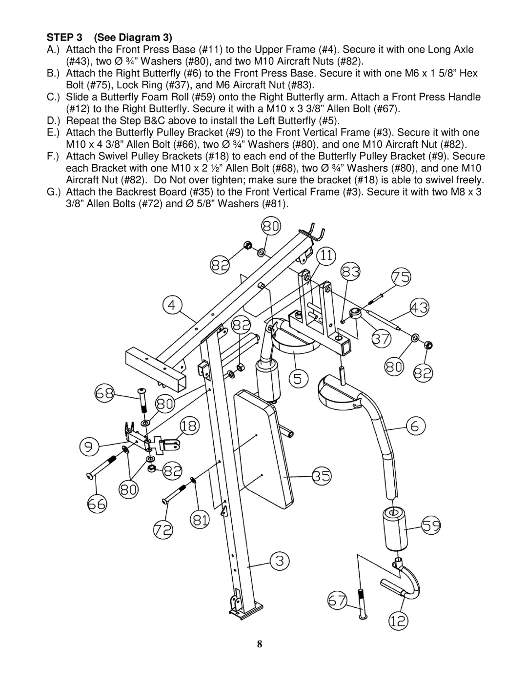
A.) Attach the Front Press Base (#11) to the Upper Frame (#4). Secure it with one Long Axle (#43), two Ø ¾” Washers (#80), and two M10 Aircraft Nuts (#82).
B.) Attach the Right Butterfly (#6) to the Front Press Base. Secure it with one M6 x 1 5/8” Hex Bolt (#75), Lock Ring (#37), and M6 Aircraft Nut (#83).
C.) Slide a Butterfly Foam Roll (#59) onto the Right Butterfly arm. Attach a Front Press Handle (#12) to the Right Butterfly. Secure it with a M10 x 3 3/8” Allen Bolt (#67).
D.) Repeat the Step B&C above to install the Left Butterfly (#5).
E.) Attach the Butterfly Pulley Bracket (#9) to the Front Vertical Frame (#3). Secure it with one M10 x 4 3/8” Allen Bolt (#66), two Ø ¾” Washers (#80), and one M10 Aircraft Nut (#82).
F.) Attach Swivel Pulley Brackets (#18) to each end of the Butterfly Pulley Bracket (#9). Secure each Bracket with one M10 x 2 ½” Allen Bolt (#68), two Ø ¾” Washers (#80), and one M10 Aircraft Nut (#82). Do Not over tighten; make sure the bracket (#18) is able to swivel freely.
G.) Attach the Backrest Board (#35) to the Front Vertical Frame (#3). Secure it with two M8 x 3 3/8” Allen Bolts (#72) and Ø 5/8” Washers (#81).
8