ASSEMBLY INSTRUCTION
Tools Required Assembling the Machine: Two Adjustable Wrenches and Allen Wrenches
NOTE: It is strongly recommended two or more people assembling this machine to avoid possible injury.
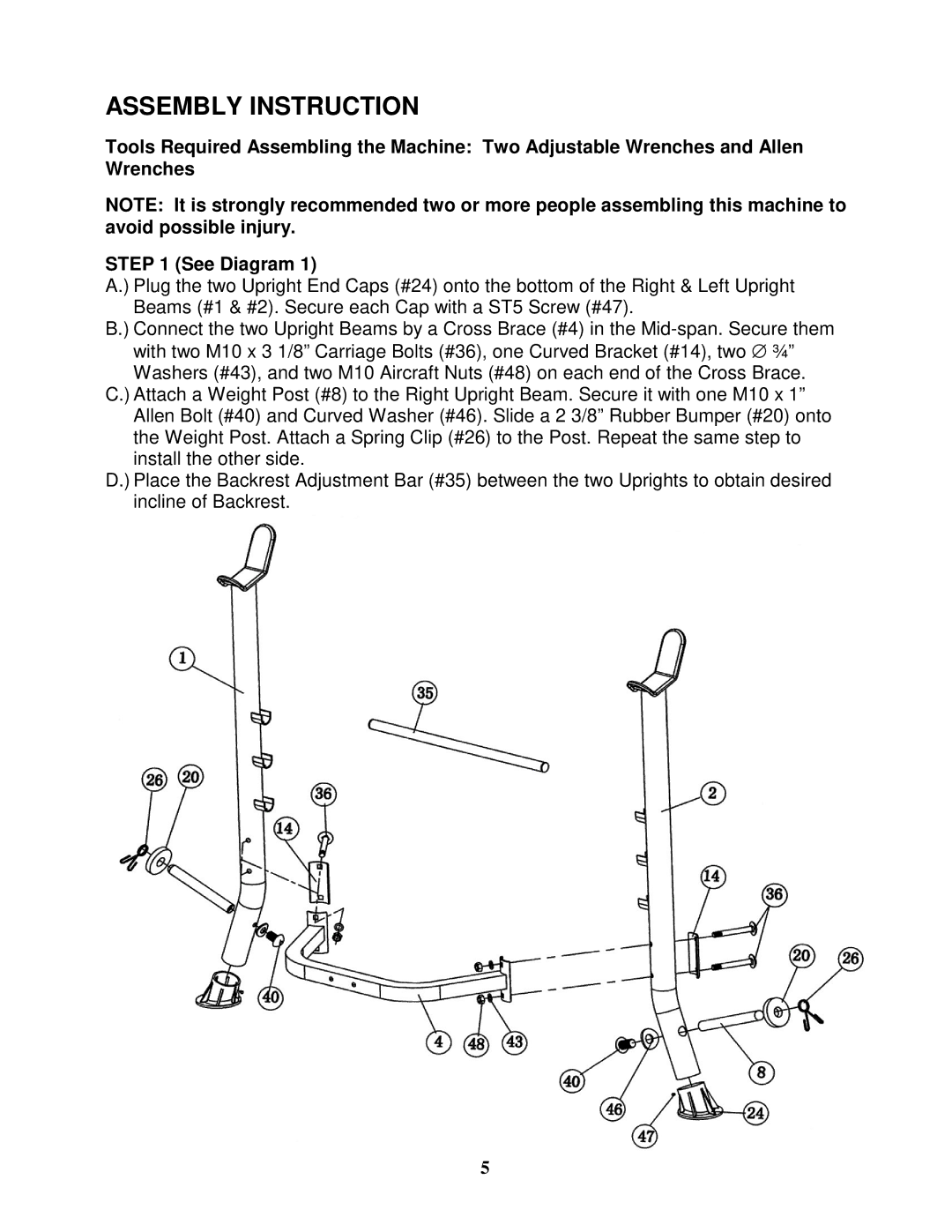
STEP 1 (See Diagram 1)
A.) Plug the two Upright End Caps (#24) onto the bottom of the Right & Left Upright Beams (#1 & #2). Secure each Cap with a ST5 Screw (#47).
B.) Connect the two Upright Beams by a Cross Brace (#4) in the
C.) Attach a Weight Post (#8) to the Right Upright Beam. Secure it with one M10 x 1” Allen Bolt (#40) and Curved Washer (#46). Slide a 2 3/8” Rubber Bumper (#20) onto the Weight Post. Attach a Spring Clip (#26) to the Post. Repeat the same step to install the other side.
D.) Place the Backrest Adjustment Bar (#35) between the two Uprights to obtain desired incline of Backrest.
5