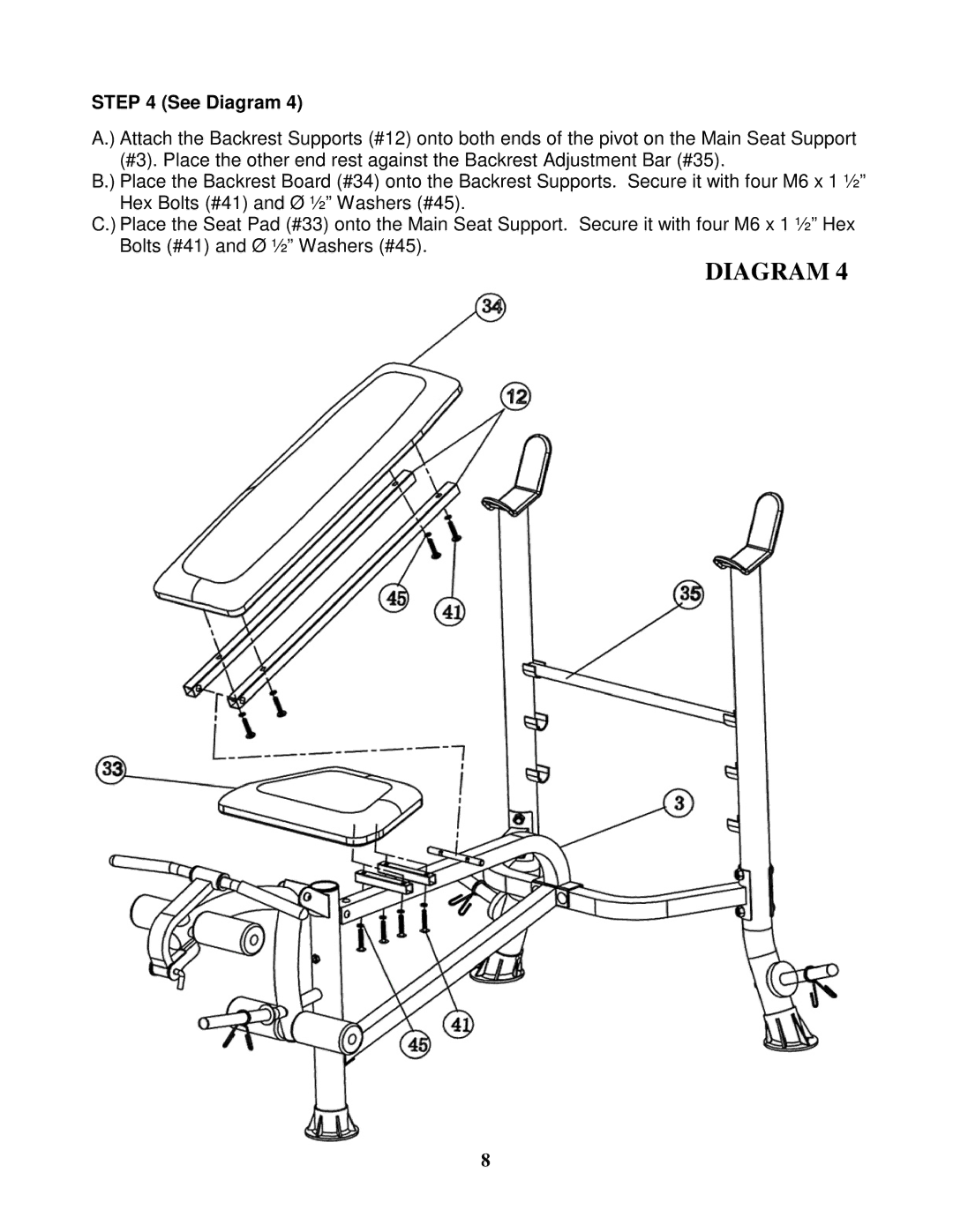
STEP 4 (See Diagram 4)
A.) Attach the Backrest Supports (#12) onto both ends of the pivot on the Main Seat Support (#3). Place the other end rest against the Backrest Adjustment Bar (#35).
B.) Place the Backrest Board (#34) onto the Backrest Supports. Secure it with four M6 x 1 ½” Hex Bolts (#41) and Ø ½” Washers (#45).
C.) Place the Seat Pad (#33) onto the Main Seat Support. Secure it with four M6 x 1 ½” Hex Bolts (#41) and Ø ½” Washers (#45).
DIAGRAM 4
8