27700B S.W. Parkway Ave.
Wilsonville, Oregon
www.infocus.com
Installation Instructions
These are the installation instructions for your Digital Projector Mount. Included are four methods of installation. Select the method that works best for your viewing situation. The methods are:
Fixed Height Ceiling Installation— best for short ceilings, eight (8’) or lower
Adjustable Height Ceiling
feet or higher *
Wall Mount
*If the required height range is greater than 12½", the optional
 Before You Start the Installation
The wall or ceiling where you want to install the digital projector must be capable of supporting a weight that is five (5) times the weight of 6lbs the
∙To avoid personal injury, use only an approved projector mount. Using an unauthorized projec tor mount may lead to poor ventilation and projector failure.
∙When installing the projector mount, keep in mind that the projector’s focus ring is not squarely in the center of the front of the projector, but offset by several inches. Make sure that when you mount the projector you offset the installation to match the amount of inches that the projector’s focus ring is offset from the center of the front of the projector.
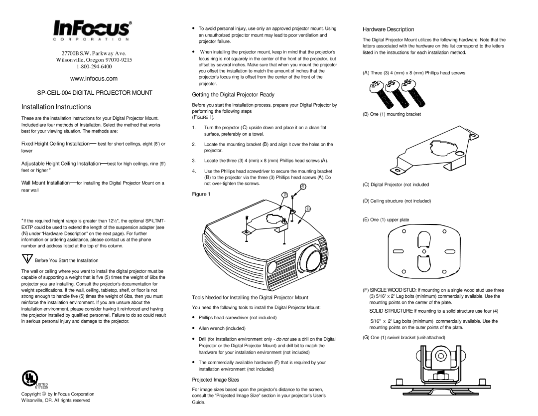
Getting the Digital Projector Ready
Before you start the installation process, prepare your Digital Projector by performing the following steps
(FIGURE 1).
1.Turn the projector ( C) upside down and place it on a clean flat surface, preferably on a towel.
2.Locate the mounting bracket (B) and align it over the holes on the projector.
3.Locate the three (3) 4 (mm) x 8 (mm) Phillips head screws (A).
4.Use the Phillips head screwdriver to secure the mounting bracket (B) to the projector via the three (3) Phillips head screws (A). Do
not | A |
|
Figure 1 | B |
| C |
Hardware Description
The Digital Projector Mount utilizes the following hardware. Note that the letters associated with the hardware on this list correspond to the letters listed in the instructions for each installation method.
(A) Three (3) 4 (mm) x 8 (mm) Phillips head screws
(B) One (1) mounting bracket
(C) Digital Projector (not included
(D) Ceiling structure (not included)
(E) One (1) upper plate
projector you are installing. Consult the projector’s documentation for weight specifications. If the wall, ceiling, tabletop, shelf, or floor is not strong enough to handle five (5) times the weight of 6lbs, then you must reinforce the installation environment. If you are unsure about the installation environment, please consider having it reinforced and having the projector installed by qualified personnel. Failure to do so could result in serious personal injury and damage to the projector.
R |
![]()
![]() LISTED
LISTED
E176225
Copyright © by InFocus Corporation
Wilsonville, OR. All rights reserved
Tools Needed for Installing the Digital Projector Mount
You need the following tools to install the Digital Projector Mount:
∙Phillips head screwdriver (not included)
∙Allen wrench (included)
∙Drill (for installation environment only - do not use a drill on the Digital Projector or the Digital Projector Mount) and drill bit to match the hardware for your installation environment (not included)
∙The commercially available hardware (F) that is required by your installation environment (not included)
Projected Image Sizes
For image sizes based upon the projector’s distance to the screen, consult the ”Projected Image Size” section in your projector’s User’s Guide.
(F) SINGLE WOOD STUD: If mounting on a single wood stud use three
(3)5/16" x 2" Lag bolts (minimum) commercially available. Use the mounting points on the center of the plate.
SOLID STRUCTURE: If mounting to a solid structure use four (4)
5/16" x 2" Lag bolts (minimum) commercially available. Use the mounting points on the outer points of the plate.
(G) One (1) swivel bracket