Installation to Extension Column | |
| Q |
| |
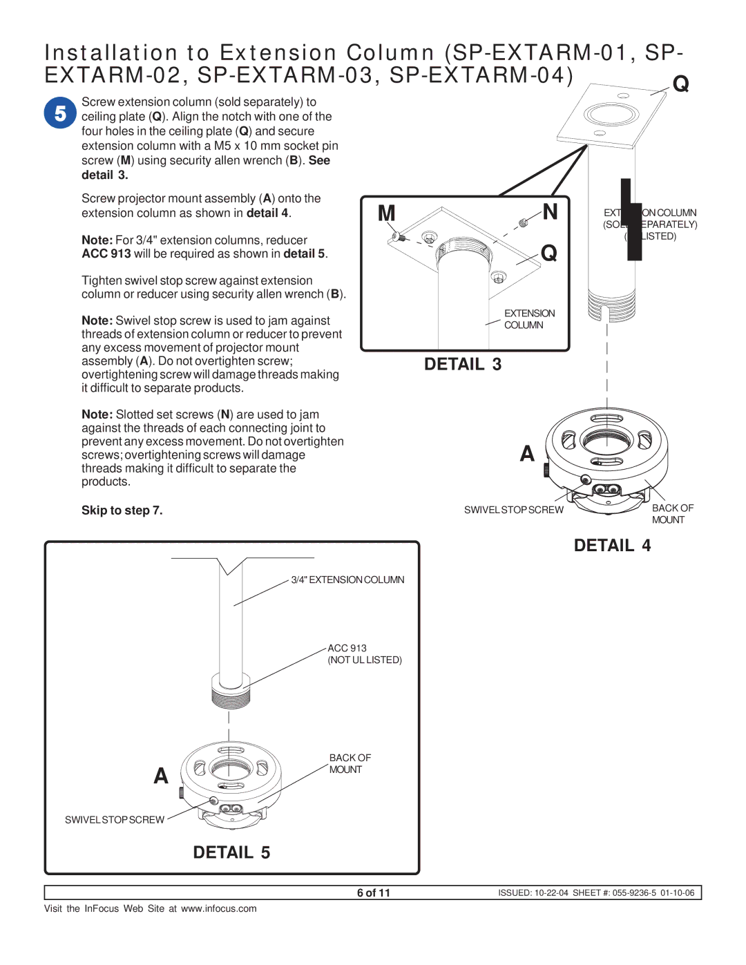
Screw extension column (sold separately) to ceiling plate (Q). Align the notch with one of the four holes in the ceiling plate (Q) and secure extension column with a M5 x 10 mm socket pin screw (M) using security allen wrench (B). See
detail 3.
Screw projector mount assembly (A) onto the | M | N |
|
extension column as shown in detail 4. | EXTENSION COLUMN | ||
| (SOLD SEPARATELY) | ||
Note: For 3/4" extension columns, reducer |
| Q | (UL LISTED) |
ACC 913 will be required as shown in detail 5. |
|
| |
Tighten swivel stop screw against extension |
|
|
|
column or reducer using security allen wrench (B). |
|
|
|
Note: Swivel stop screw is used to jam against |
| EXTENSION |
|
| COLUMN |
| |
threads of extension column or reducer to prevent |
|
|
|
any excess movement of projector mount |
| DETAIL 3 |
|
assembly (A). Do not overtighten screw; |
|
| |
overtightening screw will damage threads making |
|
|
|
it difficult to separate products. |
|
|
|
Note: Slotted set screws (N) are used to jam against the threads of each connecting joint to prevent any excess movement. Do not overtighten
screws; overtightening screws will damageA threads making it difficult to separate the
products.
Skip to step 7. | SWIVELSTOPSCREW | BACK OF |
|
| MOUNT |
DETAIL 4
3/4" EXTENSION COLUMN
ACC 913
(NOT UL LISTED)
A
SWIVELSTOPSCREW
BACK OF MOUNT
DETAIL 5
6 of 11 | ISSUED: |
Visit the InFocus Web Site at www.infocus.com