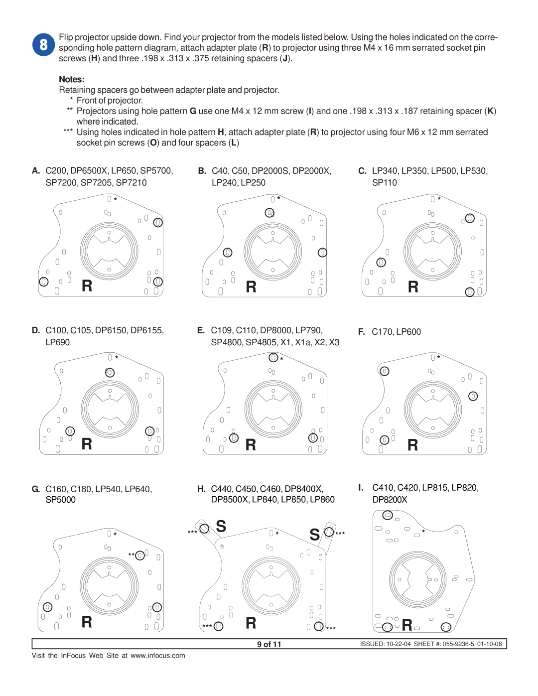
Flip projector upside down. Find your projector from the models listed below. Using the holes indicated on the corre- sponding hole pattern diagram, attach adapter plate (R) to projector using three M4 x 16 mm serrated socket pin screws (H) and three .198 x .313 x .375 retaining spacers (J).
Notes:
Retaining spacers go between adapter plate and projector.
*Front of projector.
**Projectors using hole pattern G use one M4 x 12 mm screw (I) and one .198 x .313 x .187 retaining spacer (K) where indicated.
***Using holes indicated in hole pattern H, attach adapter plate (R) to projector using four M6 x 12 mm serrated socket pin screws (O) and four spacers (L)
A. C200, DP6500X, LP650, SP5700, | B. C40, C50, DP2000S, DP2000X, | C. LP340, LP350, LP500, LP530, |
SP7200, SP7205, SP7210 | LP240, LP250 | SP110 |
* | * | * |
R | R | R |
D. C100, C105, DP6150, DP6155, | E. C109, C110, DP8000, LP790, | F. C170, LP600 |
LP690 | SP4800, SP4805, X1, X1a, X2, X3 |
|
* | * | * |
R |
|
| R |
|
| R |
G. C160, C180, LP540, LP640, | H. | C440, C450, C460, DP8400X, |
| I. C410, C420, LP815, LP820, | ||
SP5000 |
| DP8500X, LP840, LP850, LP860 |
| DP8200X | ||
* | *** | S | * | S | *** | * |
|
|
| ||||
**
R | *** | R | *** | R |
|
| 9 of 11 |
| ISSUED: |
Visit the InFocus Web Site at www.infocus.com