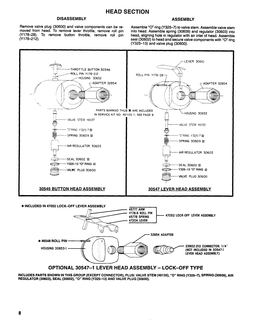
Ingersoll-Rand 7235-C, 7236-C, 7149-C manual Head Section, Disassemblyassembly, Lever Head Assembly

Models: 7235-C 7236-C 7153-C 7149-C

1 11
Download 11 pages 47.22 Kb
Page 8
Image 8

HEAD SECTION

DISASSEMBLYASSEMBLY

Remove valve plug (30600) and valve components can be re- moved from head. To remove lever throttle, remove roll pin (Y178-28). To remove button throttle, remove roll pin (Y178-212).

Assemble “O”ring (Y325-7) to valve stem. Assemble valve stem into head. Assemble spring (30609) and regulator (30603) into head, aligning hole in regulator with air inlet of head. Assemble seal (30602) to head and secure valve components with “O”ring (Y325-13) and valve plug (30600).

LEVER 30610

THROTTLE BUTTON30346

ADAPTER 328

VALVE PLUG 30600

I

30547 LEVER HEAD ASSEMBLY


JI INCLUDED IN 47052 LOCK-OFF LEVER ASSEMBLY

47052 LOCK-OFF LEVER ASSEMBLY

32654 ADAPTER

* 46548 ROLL PIN

23902-210 CONNECTOR, l/4”

HOUSING 30653-l(NOT INCLUDED IN 30547-l

LEVER HEAD ASSEMBLY)

OPTIONAL 30547-l LEVER HEAD ASSEMBLY - LOCK-OFF TYPE

INCLUDES PARTS SHOWN IN THIS GROUP (EXCEPT CONNECTOR), PLUS: VALVE STEM (46135), “O” RING (Y325-7), SPRING (30609), AIR REGULATOR (30603), SEAL (30602), “O” RING (Y325-13) AND VALVE PLUG (30600).

Page 8
Image 8
Ingersoll-Rand 7235-C, 7236-C, 7149-C, 7153-C manual Head Section, Disassemblyassembly, Lever Head Assembly