GRINDING WHEEL MOUNTING INSTRUCTIONS
M10
43
Disconnectair supply from grinder or shut off air supply and exhaust (drain)air line of compressed air before mountingor removingany abrasive wheel or wire brush, or otherwise performing maintenance or service to the tool.
Check grinder speed before mountinggrinding wheel (or other type accessory) with a reliable tachometerto makesure that the actual speed ofthe grinderdoes not exceed its rated free speed.
Checkoperatingspeedofgrindingwheel or wire brushto be usedwith the grind- er. The maximum operating speed marked on the grinding wheel, blotters or packaging, shall equal or exceed the rated free speed of the grinder.Also, the type and size of the grinding wheel or wire brush shall be compatible with the grinder size and type.
Check abrasive wheels prior to mounting for chips or cracksCracked. or chipped wheels shall not be used.
Care mustbe takenthat a grindingwheel,or wire brush,ofthe correctspeed rat- ing is used. Ratedwheel capacities forAro grinders are maximumonly.Regard- less of the rated capacity and speed of any Aro grinder,abrasive wheels or wire brushes shall never be operated at a speed greater than that recommendedby the wheel (or brush) manufacturer.
DressingAbrasive Wheels. Upon mountinga grindingwheel, the tool shouldbe operated at gradually increasing speed and checked for good balance of the wheel. If unbalance is observed, the wheel shall be dressed. If dressing fails to establish acceptable balance, the wheel shall not be used.
MOUNTING INSTRUCTIONS FOR MOUNTED WHEELS
FOR USE WITH COLLET ASSEMBLIES.
The collet shall be checked to assure it to be in good conditionand properly af- fixed to the grinder spindle.
The mandrelshall be insertedto the fulldepthofthe grippingjaws ofthecollet.At least 1/2 the mandrel length shall be inserted into the Collet.
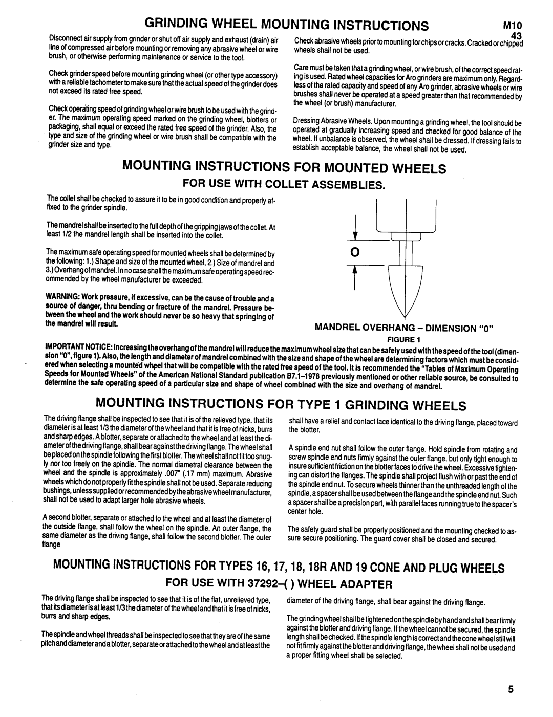
The maximumsafe operating speed for mountedwheels shall be determinedby the following: 1.) Shape and size ofthe mountedwheel, 2.) Size of mandreland
3.) Overhang ofmandrelIn.no case shall the maximum safe operating speed rec- ommended by the wheel manufacturerbe exceeded.
WARNING:Workpressure,if excessive,canbethe causeof troubleanda sourceof danger,thru bending or fractureof the mandrel.Pressurebe- tweenthewheelandthe workshould neverbeso heavythat springing of the mandrelwill result.
MANDREL OVERHANG - DIMENSION “0”
FIGURE1
IMPORTANTNOTICE:lncreaslng the overhangofthemandrelwill reducethemaximumwheelsizethatcanbesafelyusedwith thespeedofthetool(dlmen- slon “0”,figure 1).Also,thelengthanddiameterof mandrelcombinedwith thesizeandshapeofthewheelaredeterminingfactorswhich mustbeconsid- eredwhenselectinga mountedwheelthat will becompatiblewith the ratedfreespeedof thetool. It is recommendedthe “Tablesof MaximumOperating Speedsfor MountedWheels”of the AmericanNationalStandardpublication
MOUNTING INSTRUCTIONS FOR TYPE 1 GRINDING WHEELS
The driving flange shall be inspectedto see that it is of the relieved type, that its diameter is at least 1/3the diameter of the wheel and that it is free of nicks,burrs andsharp edges.A blotter,separate or attachedto the wheel and at leastthe di- ameter ofthe driving flange, shallbear againstthe driving flange. The wheel shall be placed onthe spindle followingthe firstblotter. Thewheel shall notfittoo snug- ly nor too freely on the spindle. The normal diametral clearance between the wheel and the spindle is approximately ,007” (.17 mm) maximum. Abrasive wheelswhichdo notproperlyfit the spindle shall not be used.Separate reducing bushings,unlesssuppliedorrecommendedbytheabrasive wheelmanufacturer, shall not be used to adapt larger hole abrasive wheels.
A second blotter,separate or attached to the wheel and at least the diameter of the outside flange, shall follow the wheel on the spindle. An outer flange, the same diameter as the driving flange, shall follow the second blotter. The outer flange
shall have a relief and contact face identical to the driving flange, placedtoward the blotter.
A spindle end nut shall follow the outer flange. Hold spindle from rotating and screw spindle end nuts firmly against the outer flange, but only tight enough to insuresufficientfrictiononthe blotterfacesto drivethe wheel. Excessivetighten- ing can distortthe flanges. The spindle shall project flushwith or past the end of the spindle end nut.Tosecure wheels thinnerthan the unthreadedlengthof the spindle,a spacer shallbe usedbetweenthe flange andthe spindle end nut. Such a spacershall be a precisionpart, with parallel faces runningtrue to the spacer’s center hole.
The safety guard shall be properly positioned and the mountingchecked to as- sure secure positioning. The guard cover shall be closed and secured.
MOUNTINGINSTRUCTIONSFORTYPES16, 17, 18, 18RAND19CONEANDPLUGWHEELS
FOR USE WITH 37292-( ) WHEEL ADAPTER
The driving flange shall be inspectedto see that it is of the flat, unrelievedtype, | diameter of the driving flange, shall bear against the driving flange. |
thatitsdiameter isleastat 1/3 the diameterofthewheel and thatit isfree ofnicks, |
|
burrsandsharpedges. | Thegrindingwheelshall betightenedonthe spindleby hand and shallbearfirmly |
| againstthe blotter anddriving flange. Ifthe wheel cannotbe secured,the spindle |
The spindle and wheel threads shall be inspected to see that they are ofthe samelength shallbe checked.Ifthe spindle length iscorrect and the cone wheel stillwill
pitchand diameteranda blotter,separate or attachedtothewheelandat leastthe | notfitfirmlyagainstthe blotterand drivingflange,the wheelshall notbe usedand |
| a proper fitting wheel shall be selected. |
5