Maintenance
Dissassembly
Head Disassembly
To remove head section from housing without disassembling head components, remove head with control rod (59) attached to gear (25). To accomplish this -
-Remove two screws (96) and housing cap (95).
-Drive out roll pin (61) and remove brake block (60).
-Drive out roll pin (69) from control arm (68).
-Remove six screws (22) and washers (23).
-Remove head section and control rod from housing as one unit.
To disassemble head components without removing head section from hoist:
-Remove two screws (96) and housing cap (95).
-Drive out roll pin (69) from control arm (68).
-Drive out roll pin (26) from gear (25) and drive control rod (59) back thru gear (25) and remove gear.
-Remove adapters (19), valves (17) and (29) and valve body (15).
-Remove set screws (24) and regulator valves (28).
CAUTION
do not attempt to adjust or remove regulator valves (28) from
-Remove adapter (1) and screen (2).
-Remove retaining ring (4), swivel (3), swivel body (6) and screen (8).
-Remove two screws (9), washers (10), exhaust deflector (11), screen (12) and muffler filler (13).
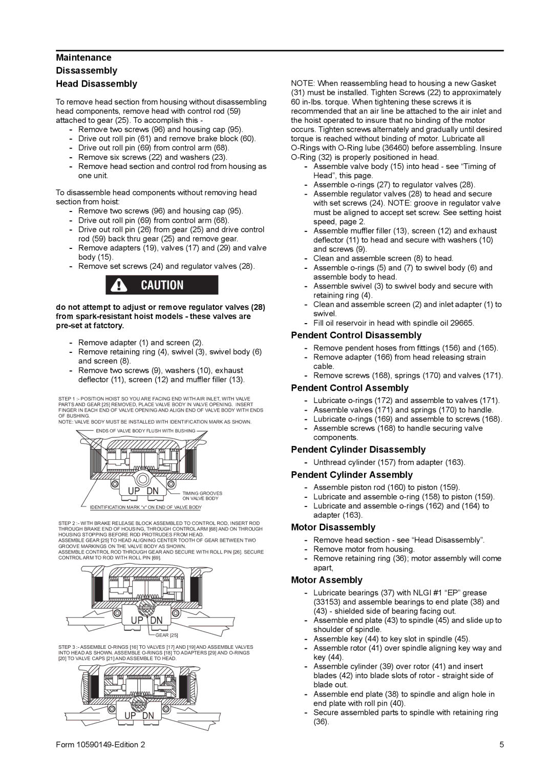
STEP 1 :- POSITION HOIST SO YOU ARE FACING END WITH AIR INLET, WITH VALVE PARTS AND GEAR [25] REMOVED, PLACE VALVE BODY IN VALVE OPENING. INSERT FINGER IN EACH END OF VALVE OPENING AND ALIGN END OF VALVE BODY WITH ENDS OF BUSHING.
NOTE: VALVE BODY MUST BE INSTALLED WITH IDENTIFICATION MARK AS SHOWN.
ENDS OF VALVE BODY FLUSH WITH BUSHING
UP DN | TIMING GROOVES |
| ON VALVE BODY |
IDENTIFICATION MARK "x" ON END OF VALVE BODY
STEP 2 :- WITH BRAKE RELEASE BLOCK ASSEMBLED TO CONTROL ROD, INSERT ROD THROUGH BRAKE END OF HOUSING, THROUGH CONTROL ARM [68] AND ON THROUGH HOUSING STOPPING BEFORE ROD PROTRUDES FROM HEAD.
ASSEMBLE GEAR [25] TO HEAD ALIGNING CENTER TOOTH OF GEAR BETWEEN TWO GROOVE MARKINGS ON THE VALVE BODY AS SHOWN.
ASSEMBLE CONTROL ROD THROUGH GEAR AND SECURE WITH ROLL PIN [26]. SECURE CONTROL ARM TO ROD WITH ROLL PIN [69].
UP DN
GEAR [25]
STEP 3 :- ASSEMBLE
UP DN
Form
NOTE: When reassembling head to housing a new Gasket
(31)must be installed. Tighten Screws (22) to approximately 60
-Assemble valve body (15) into head - see “Timing of Head”, this page.
-Assemble
-Assemble regulator valves (28) to head and secure with set screws (24). NOTE: groove in regulator valve must be aligned to accept set screw. See setting hoist speed, page 2.
-Assemble muffler filler (13), screen (12) and exhaust deflector (11) to head and secure with washers (10) and screws (9).
-Clean and assemble screen (8) to head.
-Assemble
-Assemble swivel (3) to swivel body and secure with retaining ring (4).
-Clean and assemble screen (2) and inlet adapter (1) to swivel.
-Fill oil reservoir in head with spindle oil 29665.
Pendent Control Disassembly
-Remove pendent hoses from fittings (156) and (165).
-Remove adapter (166) from head releasing strain cable.
-Remove screws (168), springs (170) and valves (171).
Pendent Control Assembly
-Lubricate
-Assemble valves (171) and springs (170) to handle.
-Lubricate
-Assemble screws (168) to handle securing valve components.
Pendent Cylinder Disassembly
-Unthread cylinder (157) from adapter (163).
Pendent Cylinder Assembly
-Assemble piston rod (160) to piston (159).
-Lubricate and assemble
-Lubricate and assemble
Motor Disassembly
-Remove head section - see “Head Disassembly”.
-Remove motor from housing.
-Remove retaining ring (36); motor assembly will come apart,
Motor Assembly
-Lubricate bearings (37) with NLGI #1 “EP” grease (33153) and assemble bearings to end plate (38) and
(43)- shielded side of bearing facing out.
-Assemble end plate (43) to spindle (45) and slide up to shoulder of spindle.
-Assemble key (44) to key slot in spindle (45).
-Assemble rotor (41) over spindle aligning key way and key (44).
-Assemble cylinder (39) over rotor (41) and insert blades (42) into blade slots of rotor - straight side of blade out.
-Assemble end plate (38) to spindle and align hole in end plate with roll pin (40).
-Secure assembled parts to spindle with retaining ring
5