HEAD SECTION | M30 |
| 33 |
DISASSEMBLY
a.Remove roll pin
b.Remove screw
c.Grasp end of valve assembly (47880) and pull to remove valve assembly and bushing (45465).
d.Remove retaining ring
ASSEMBLY
NOTE: Whenever a part containing “O”rings has been removed from the tool, it is recommended the “O” rings be replaced. Grease all “O”rings before assembly.
a. Assemble “O”rings
bushings (45465).
b.Assemble “O”ring
c.Lubricate plunger (47879) and valve assembly (47860) with ARO 29665 spindle oil.
d.Assemble springs
e.Assemble plungers (47879) and valve assemblies (47880) to bushings (45465) and assemble bushings to housing, align- ing flats of bushings with flats of shroud.
f.Assemble shroud (45468) to housing, securing with screw
g.Assemble trigger to shroud, securing with roll pin
h.Assemble muffler (45474) and screens (42911) to housing, securing with retaining ring
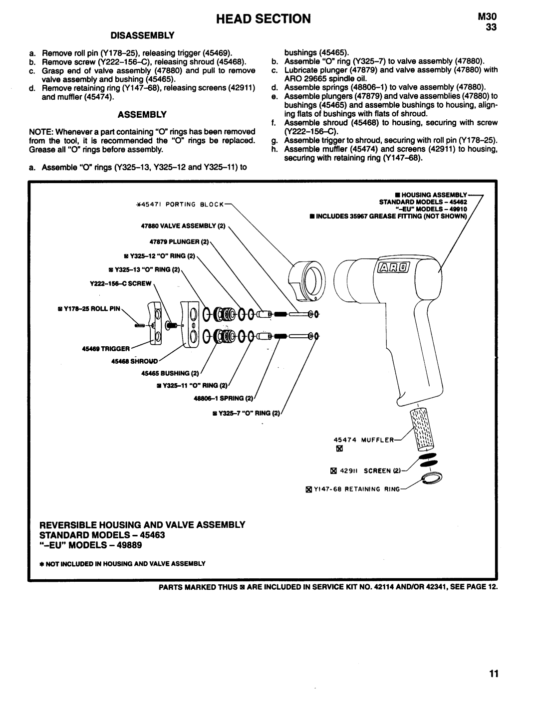
n HOUSING ASSEMBLY
45471 PORTING BLOCKSTANDARD MODELS - 49492
47990 VALVE ASSEMBLY (2)
47979 PLUNGER (2)
45469 TRIGGER
45465 BUSHING (2)
45474 MUFFLER
q 42911 SCREEN (2)
REVERSIBLE HOUSING AND VALVE ASSEMBLY STANDARD MODELS - 45463
“-EU” MODELS - 49889
* NOT INCLUDED IN HOUSING AND VALVE ASSEMBLY
PARTS MARKED THUS ARE INCLUDED IN SERVICE KIT NO. 42114 AND/OR 42341, SEE PAGE 12.
11
